Difference between revisions of "FFT Spectrum Analyzer Multipurpose"
| (40 intermediate revisions by 2 users not shown) | |||
| Line 1: | Line 1: | ||
{{#seo: | {{#seo: | ||
|title=FFT Spectrum | |title=FFT Spectrum analyzer for acoustic and vibration - Modal analysis | ||
|keywords= FFT analyzer, vibration analyzer, Spectrum analyzer, analyzer acoustic and vibration, Octave analyzer, third octave, FFT analysis software, order tracking measurement, turbomachinery Orbit, fast fourier transform, modal analysis | |||
|keywords= FFT analyzer, Spectrum analyzer, analyzer acoustic and vibration, Octave analyzer, FFT analysis software | |description= OROS portable hardware multichannels Instrument with real time software, easy to operate . | ||
|description= | |image=FFT_analyzer_hardware_2.webp | ||
|image= | |||
}} | }} | ||
__NOTOC__ | __NOTOC__ | ||
[[File: | [[File:O4_range Gamme O4 + OR10 + OR35 + OR36 + OR38.png|frame|left|FFT analyzers|alt=Analyzer acoustic vibration multichannel]] | ||
The OROS series multi-function FFT analyzer is PC-based, high-performance, high reliability and easy to operate. | The OROS series multi-function FFT analyzer is PC-based, high-performance, high reliability and easy to operate. | ||
We have further increased the arithmetic processing speed and increased the real-time analysis capacity to more than 16 times that of the conventional model (OR20 series). An ethernet LAN cable is used as the interface. | We have further increased the arithmetic processing speed and increased the real-time analysis capacity to more than 16 times that of the conventional model (OR20 series). An ethernet LAN cable is used as the interface. | ||
In addition, the number of simultaneous recording channels in the frequency range (40 kHz) has been expanded to a maximum of 1000 channels and the dynamic range has been improved to 140 dB | In addition, the number of simultaneous recording channels in the frequency range (40 kHz) has been expanded to a maximum of 1000 channels and the dynamic range has been improved to 140 dB. These improvements allow a user to measure time signals over a wide frequency range simultaneously on multiple channels. | ||
| Line 25: | Line 22: | ||
<gallery gallery mode="packed-hover" align= left > | <gallery gallery="" mode="packed-hover" align="left"> | ||
TWanalyzer2.jpg|Analyzer Cascade mode | File:TWanalyzer2.jpg|alt=Vibration measurement up to 1000 channels|Analyzer Cascade mode | ||
File:Situation auto hammer pc.jpg|alt=Hammer test on automative in anechoic room|Modal FRF measurement | |||
File:Auto anechoic chamber2.webp|alt=Sound intensiyt measurement in anechoic room|Acoustic Sound intensity | |||
File:Turbo orbit.JPG|alt=Turbomachinery orbit vibration measurement|Vibration on trubomachinery | |||
File:Or34 situation.jpg|alt=NVH measurement on a car|NVH automotive measurement | |||
File:Airfrance.jpg|alt=Acoutic measurement with octave anlyzer in a plane|In flight measurement | |||
</gallery> | </gallery> | ||
| Line 45: | Line 42: | ||
* Equipped with an output channel as a standard | * Equipped with an output channel as a standard | ||
* Built-in internal battery as a standard | * Built-in internal battery as a standard | ||
* Record, | * Record, Fast Fourier Transform analysis, octave analysis, and tracking analysis can be performed simultaneously at high sampling frequencies | ||
* Realtime measurements and post-analysis can be performed with the same software platform ([[NVGate]]) | * Realtime measurements and post-analysis can be performed with the same software platform ([[NVGate]]) | ||
* In addition to sound and vibration, strain and temperature can be measured at the same time using XPODS (**) | * In addition to sound and vibration, strain and temperature can be measured at the same time using XPODS (**) | ||
| Line 61: | Line 58: | ||
==Introducing the hardware== | ==Introducing the hardware== | ||
[[File:hardware.png|right|Spectrum analyzer|alt=OROS instrument analyzer for noise and vibration]] | |||
===Small and lightweight=== | |||
OR10-8ch model: 0.8kg | OR10-8ch model: 0.8kg | ||
O4: 4ch model: 0.5kg | |||
OR35 TW: 10ch model: 3.0kg | |||
OR36 TW: 16ch model: 5.2kg | OR36 TW: 16ch model: 5.2kg | ||
OR38 TW: 32ch model: 8.2kg | OR38 TW: 32ch model: 8.2kg | ||
<br> | |||
<br> | |||
<br> | |||
<br> | <br> | ||
<br> | <br> | ||
| Line 79: | Line 79: | ||
===Ethernet LAN interface=== | ===Ethernet LAN interface=== | ||
[[image:laninterface.PNG|right|FFT analyzer ethernet]] | [[image:laninterface.PNG|right|FFT analyzer ethernet|alt=Back of FFT analyzer : ethernet connection for PC]] | ||
Achieves high-speed communication with a PC through an ethernet LAN interface | Achieves high-speed communication with a PC through an ethernet LAN interface | ||
<br> | <br> | ||
| Line 89: | Line 89: | ||
===Built-in battery=== | ===Built-in battery=== | ||
OR10 | OR10/ OR35/ TW OR36 / TW OR38: Models have a built-in battery. | ||
OR10 can be operated by battery for 4hours | OR10 can be operated by battery for 4hours | ||
| Line 96: | Line 96: | ||
TW OR36 / TW OR38 can be operated by battery for 2 hours. | TW OR36 / TW OR38 can be operated by battery for 2 hours. | ||
04 operate with battery PC. | |||
===External battery=== | ===External battery=== | ||
[[File:external battery.PNG|200px|right|external battery on analyzer]] | [[File:external battery.PNG|200px|right|external battery on analyzer|alt=External battery on spetrum analyzer]] | ||
We provide a compact and lightweight external battery that can be installed on all models. | We provide a compact and lightweight external battery that can be installed on all models. | ||
| Line 123: | Line 125: | ||
=== Measure From Sound / Vibration and Strain Gauge / Temperature === | === Measure From Sound / Vibration and Strain Gauge / Temperature === | ||
(OR35 / TW OR36 / TW OR38 only) | (OR35 / TW OR36 / TW OR38 only) | ||
[[File:Usersmanual_32.jpg|200px|right|Conditioner on analyzer]] | [[File:Usersmanual_32.jpg|200px|right|Conditioner on analyzer|alt=Temperature and straing conditionner]] | ||
By mounting a [[XPod_Bridge_-_Strain_gauge|strain gauge conditioner]] and [[NVGate_X-Pod:_Temperature_probe_conditioner|thermocouple conditioner]] on the Oros FFT analyzer, it is possible to measure strain and temperature data in addition to sound and vibration data. | By mounting a [[XPod_Bridge_-_Strain_gauge|strain gauge conditioner]] and [[NVGate_X-Pod:_Temperature_probe_conditioner|thermocouple conditioner]] on the Oros FFT analyzer, it is possible to measure strain and temperature data in addition to sound and vibration data. | ||
| Line 133: | Line 135: | ||
===CAN-bus Module Available === | ===CAN-bus Module Available === | ||
[[File:Can_Bus.jpg|150px|right|Can bus measurement]] | [[File:Can_Bus.jpg|150px|right|Can bus measurement|alt=Can bus to add on OROS instrument]] | ||
(OR10/ TW OR35 / TW OR36 / TW OR38 only) | (OR10/ TW OR35 / TW OR36 / TW OR38 only) | ||
| Line 143: | Line 145: | ||
(OR35 / TW OR36 / TW OR38 only) | (OR35 / TW OR36 / TW OR38 only) | ||
[[File:d_rec.PNG|150px|right|Data acquisition recorder]] | [[File:d_rec.PNG|150px|right|Data acquisition recorder|alt=Vibration time signal Measurement without PC]] | ||
The FFT analyzer is equipped with a [[NVGate_D-Rec|record-only button]]. Simply select a predefined measurement setup and press the record button to record onto the FFT analyzer alone without the use of a PC. | The FFT analyzer is equipped with a [[NVGate_D-Rec|record-only button]]. Simply select a predefined measurement setup and press the record button to record onto the FFT analyzer alone without the use of a PC. | ||
| Line 152: | Line 154: | ||
[[File:FFT_analyzer.jpg|600px|Back of the hardware]] | In addition, the back of the Fast Fourier Transform Spectrum Analyzer Multipurpose is equipped with an audio terminal and power supply. It is possible to record audio data while also measuring the time signal. The analyzer also can supply power to required sensors, such as proximity probes, tachometers and DC sensors. | ||
[[File:FFT_analyzer.jpg|600px|Back of the hardware|alt=all the plug available on the backside of instrment]] | |||
<br> | <br> | ||
<br> | <br> | ||
| Line 174: | Line 177: | ||
The Oros series FFT spectrum analyzer multifunction uses an interface similar to the ribbon interface used by Microsoft Office. All menus are accessible via the ribbon interface, making it easy to change measurement settings. | The Oros series FFT spectrum analyzer multifunction uses an interface similar to the ribbon interface used by Microsoft Office. All menus are accessible via the ribbon interface, making it easy to change measurement settings. | ||
[[File:home3.PNG|800px|software ribbon]] | [[File:home3.PNG|800px|software ribbon|alt=NVgate ribbon technology]] | ||
===One-click Setting Function=== | ===One-click Setting Function=== | ||
| Line 180: | Line 183: | ||
[[File:FFT_analyzer_spectrum.png|500px|FFT spectrum]] | [[File:FFT_analyzer_spectrum.png|500px|FFT spectrum|alt=Parameters easy to change]] | ||
===Control Panel=== | ===Control Panel=== | ||
In addition, the OROS FFT spectrum analyzer is equipped with a control panel function that allows users to save frequently used measurement settings for quick access. By using this function, all settings can be changed on the [[NVGate_Control_Panel|control panel]]. For example, the following is the setting screen for a hammer test. By saving the input settings, threshold settings, and FFT analysis settings to the control panel as shown below, it is possible to make all the necessary settings quickly by only using the control panel. | In addition, the OROS FFT spectrum analyzer is equipped with a control panel function that allows users to save frequently used measurement settings for quick access. By using this function, all settings can be changed on the [[NVGate_Control_Panel|control panel]]. For example, the following is the setting screen for a hammer test. By saving the input settings, threshold settings, and FFT analysis settings to the control panel as shown below, it is possible to make all the necessary settings quickly by only using the control panel. | ||
[[File:control pannel_test.png|700px|Software FFT settings]] | [[File:control pannel_test.png|700px|Software FFT settings|alt=Control easily the software]] | ||
===Various filters can be applied to recorded signals & FFT analysis results=== | ===Various filters can be applied to recorded signals & FFT analysis results=== | ||
| Line 196: | Line 199: | ||
Any order component can be extracted in real time from the color spectrum graph. | Any order component can be extracted in real time from the color spectrum graph. | ||
[[File:extraction.jpg|Synchronous order analysis extraction]] | [[File:extraction.jpg|Synchronous order analysis extraction|alt=order extraction on vibration software]] | ||
Easy-to-read Layout | Easy-to-read Layout | ||
| Line 213: | Line 216: | ||
'''Layout 1''': Record waveform, FFT analysis result, order ratio analysis result displayed | '''Layout 1''': Record waveform, FFT analysis result, order ratio analysis result displayed | ||
[[File:Fft_extraction_data.jpg|Order extraction]] | [[File:Fft_extraction_data.jpg|Order extraction|alt=Recorder and FFT together]] | ||
'''Layout 2''': Display 3D frequency analysis results and 3D order ratio analysis results | '''Layout 2''': Display 3D frequency analysis results and 3D order ratio analysis results | ||
[[File:waterfall_extract_order.jpg|3d display order spectrum ]] | [[File:waterfall_extract_order.jpg|3d display order spectrum |alt=NVGate software on line measurement]] | ||
| Line 225: | Line 228: | ||
'''Layout 3''': Display 3D '''octave analyzer''' analysis results | '''Layout 3''': Display 3D '''octave analyzer''' analysis results | ||
[[File:octave waterfall.jpg|Octave acoustic measurement 3d display]] | [[File:octave waterfall.jpg|Octave acoustic measurement 3d display|alt=Acoustic measurement with octave]] | ||
===Easy operation <Graph layout selection button>=== | ===Easy operation <Graph layout selection button>=== | ||
| Line 232: | Line 235: | ||
You can easily arrange windows just by selecting the grid menu. | You can easily arrange windows just by selecting the grid menu. | ||
[[File:gridwindows_PNG.PNG|NVGate icone]] | [[File:gridwindows_PNG.PNG|NVGate icone|alt=Grid icone]] | ||
Batch copy of measurement data with one menu. Numerical data can be transferred to Excel all at once. | Batch copy of measurement data with one menu. Numerical data can be transferred to Excel all at once. | ||
[[File:excel_report.jpg|400px|FFT spectrum Report function]] | [[File:excel_report.jpg|400px|FFT spectrum Report function|alt=export your data]] | ||
| Line 249: | Line 252: | ||
Simply click the report button located on the ribbon interface to create a [[NVGate_Report|report]] file containing the current measurement results. | Simply click the report button located on the ribbon interface to create a [[NVGate_Report|report]] file containing the current measurement results. | ||
[[File:allwindows_.PNG|NVGate report]] | [[File:allwindows_.PNG|NVGate report|alt=report all windows]] | ||
• The content of the report is customizable. Customize it to the format that best suits your needs. | • The content of the report is customizable. Customize it to the format that best suits your needs. | ||
[[File:report-customize.jpg|500px|customize FFT analyzer software report]] | [[File:report-customize.jpg|500px|customize FFT analyzer software report|alt=Post analysis vibration software]] | ||
===Measurement data search function=== | ===Measurement data search function=== | ||
[[File:pc cloud.PNG|right|Data stored]] | [[File:pc cloud.PNG|right|Data stored|alt=cloud vibration data]] | ||
Various information (meta-data) can be added when saving measurement data. | Various information (meta-data) can be added when saving measurement data. | ||
You then can search for measurement data and projects based on the added information. | You then can search for measurement data and projects based on the added information. | ||
| Line 267: | Line 270: | ||
* Measurement site | * Measurement site | ||
* User | * User | ||
[[File:filter_project.PNG|550px|meta data on noise and vibration software NVGate]] | [[File:filter_project.PNG|550px|meta data on noise and vibration software NVGate|alt=Acoustic and vibration search function]] | ||
===Fail judgment function as standard=== | ===Fail judgment function as standard=== | ||
| Line 274: | Line 277: | ||
In the example below, a dialog is displayed when the product fails, but it is also possible to output a contact signal instead of the dialog. | In the example below, a dialog is displayed when the product fails, but it is also possible to output a contact signal instead of the dialog. | ||
[[File:fail_test.JPG|Pass/fail test on resonnance frequency impact hammer test]] | [[File:fail_test.JPG|Pass/fail test on resonnance frequency impact hammer test|alt=Failed pass test on resonnance frequency test]] | ||
===Automate post-analysis processing=== | ===Automate post-analysis processing=== | ||
| Line 281: | Line 284: | ||
[[File:BPP2.jpg|Post processing acoustic measurement batch ]] | [[File:BPP2.jpg|Post processing acoustic measurement batch |alt=Offline measurement]] | ||
==specification== | ==specification== | ||
| Line 288: | Line 291: | ||
{| class=wikitable style="width:100%;" style="text-align:center;" | {| class=wikitable style="width:100%;" style="text-align:center;" | ||
! style="width:15%| | ! style="width:15%| | ||
! style="width:17%| | ! style="width:17%|O4 | ||
! style="width:17%|OR10 | ! style="width:17%|OR10 | ||
! style="width:17%|OR35 | ! style="width:17%|OR35 | ||
| Line 305: | Line 308: | ||
! Terminal shape | ! Terminal shape | ||
| colspan=1| BNC | | colspan=1| BNC | ||
| colspan=1| Lemo (deliverd with Lemo to BNC cable) | | colspan=1| Lemo (deliverd with "Lemo to BNC" cable) | ||
| colspan=3| BNC | | colspan=3| BNC | ||
|- | |- | ||
| Line 315: | Line 318: | ||
|- | |- | ||
! Input voltage range | ! Input voltage range | ||
|colspan=5| +/-: 100mV to +/-: 40V (auto range function) | |||
|colspan= | |||
|- | |- | ||
! Maximum voltage | ! Maximum voltage | ||
|colspan=5| 60V | |||
|colspan= | |||
|- | |- | ||
!Anti-Aliasing filter | !Anti-Aliasing filter | ||
| Line 332: | Line 333: | ||
|- | |- | ||
!Dynamic range | !Dynamic range | ||
|colspan=5| | |colspan=5| >140dB | ||
|- | |- | ||
!Channels-to-channels phase accuracy | !Channels-to-channels phase accuracy | ||
|colspan=5| ± 0.02 ° (10V, 20kHz range | |colspan=5| ± 0.02 ° (10V, 20kHz range) | ||
|- | |- | ||
!Input filter | !Input filter | ||
|colspan=5| Acoustic A, C | |colspan=5| Acoustic A, C, Z, low pass, high pass, band pass, integrator, differentiator, time axis integration function | ||
|- | |- | ||
!Sampling frequency of the signal | !Sampling frequency of the signal | ||
| Line 353: | Line 354: | ||
|- | |- | ||
!Voltage range | !Voltage range | ||
| | |colspan54|+/- 300mV 40V | ||
|- | |- | ||
!colspan=6| DC input | !colspan=6| DC input | ||
| Line 405: | Line 405: | ||
|- | |- | ||
!Analysis frequency range | !Analysis frequency range | ||
|colspan= | |colspan=1|0.8Hz-100kHz | ||
|colspan=4|0.8Hz-40kHz | |||
|- | |- | ||
!FFT block size | !FFT block size | ||
| Line 522: | Line 523: | ||
|- | |- | ||
!Number of output channels | !Number of output channels | ||
|colspan=1| 1ch | |colspan=1| 1ch (lemo conector, include) | ||
|colspan=1| no output | |colspan=1| no output | ||
|colspan=1| 2ch | |colspan=1| 2ch | ||
| Line 550: | Line 551: | ||
|- | |- | ||
!Frequency range | !Frequency range | ||
|colspan=1|~ | |colspan=1|~ 100kHz | ||
|colspan=1| | |colspan=1| | ||
|colspan=3|~ 40kHz | |colspan=3|~ 40kHz | ||
| Line 586: | Line 587: | ||
|- | |- | ||
!Dimensions (width x height x depth mm) | !Dimensions (width x height x depth mm) | ||
| | |35 x 110 x 185 | ||
|37 x 174 x 120 | |37 x 174 x 120 | ||
|56 × 246 × 222 | |56 × 246 × 222 | ||
| Line 593: | Line 594: | ||
|- | |- | ||
!Weight | !Weight | ||
| | | 0.5kg | ||
| 0.85kg | | 0.85kg | ||
| 2.8kg | | 2.8kg | ||
| Line 605: | Line 606: | ||
|- | |- | ||
!DC | !DC | ||
| | | USB 3.0 type C 5V | ||
| USB 15V | | USB 15V | ||
| 10V-28V, 20VA | | 10V-28V, 20VA | ||
| Line 612: | Line 613: | ||
|- | |- | ||
!DC battery internal operating time (built-in) | !DC battery internal operating time (built-in) | ||
| | | NA : using PC battery | ||
| 4h | | 4h | ||
| 3h | | 3h | ||
| Line 619: | Line 620: | ||
|- | |- | ||
!Recommended operating temperature range | !Recommended operating temperature range | ||
|colspan= | |colspan=3| 0 ℃ ~ 40 ℃ | ||
|colspan=3| 0 ℃ ~ 50 ℃ | |||
|0 ℃ ~ 45 ℃ | |0 ℃ ~ 45 ℃ | ||
|- | |- | ||
!cooling fan | !cooling fan | ||
|colspan=1| | |colspan=1|Fan less | ||
|colspan=1|Fan less | |colspan=1|Fan less | ||
|colspan=4|Automatic control by built-in temperature sensor, forced stop possible (however, forced ON when the temperature rises above 50 ° C) | |colspan=4|Automatic control by built-in temperature sensor, forced stop possible (however, forced ON when the temperature rises above 50 ° C) | ||
| Line 662: | Line 664: | ||
| [[File:REF-MAN VOL1 Analyzer Settings Browser wiki partA 10.png]] [[NVGate_Recorder|Signal record and post analysis]] | | [[File:REF-MAN VOL1 Analyzer Settings Browser wiki partA 10.png]] [[NVGate_Recorder|Signal record and post analysis]] | ||
|- | |- | ||
| [[File:REF-MAN VOL1 Analyzer Settings Browser wiki partA 12.png]] [[ | | [[File:REF-MAN VOL1 Analyzer Settings Browser wiki partA 12.png]] [[NVGate_FFT|Resonance frequency by impact hammer]] | ||
|- | |- | ||
| [[File:REF-MAN VOL1 Analyzer Settings Browser wiki partA 12.png]] [[ORBIGate|Vibration | | [[File:REF-MAN VOL1 Analyzer Settings Browser wiki partA 12.png]] [[ORBIGate|Vibration on rotordynamics (orbit,...)]] | ||
|- | |- | ||
| [[File:REF-MAN VOL1 Analyzer Settings Browser wiki partA 12.png]] [[Modal|Modal | | [[File:REF-MAN VOL1 Analyzer Settings Browser wiki partA 12.png]] [[Modal|Modal Analysis]] | ||
|- | |- | ||
| [[File:REF-MAN VOL1 Analyzer Settings Browser wiki partA 12.png]] [[Sound_Power|Sound Power]] | | [[File:REF-MAN VOL1 Analyzer Settings Browser wiki partA 12.png]] [[Sound_Power|Sound Power]] | ||
| Line 675: | Line 677: | ||
{| class="wikitable" | {| class="wikitable" | ||
|- | |- | ||
| [[File:REF-MAN VOL1 Analyzer Settings Browser wiki partA 12.png]] [[ | | [[File:REF-MAN VOL1 Analyzer Settings Browser wiki partA 12.png]] [[NVGate_FFT|Frequency analysis, spectrum analysis]] | ||
|- | |- | ||
| [[File:REF-MAN VOL1 Analyzer Settings Browser wiki partA 12.png]] [[NVGate_Octave_Analyzer|Noise / acoustic analysis]] | | [[File:REF-MAN VOL1 Analyzer Settings Browser wiki partA 12.png]] [[NVGate_Octave_Analyzer|Noise / acoustic analysis]] | ||
| Line 681: | Line 683: | ||
| [[File:REF-MAN VOL1 Analyzer Settings Browser wiki partA 10.png]] [[NVGate_D-Rec|Time series analysis (data logger)]] | | [[File:REF-MAN VOL1 Analyzer Settings Browser wiki partA 10.png]] [[NVGate_D-Rec|Time series analysis (data logger)]] | ||
|- | |- | ||
| [[File:REF-MAN VOL1 Analyzer Settings Browser wiki partA 12.png]] [[NVGate_Synchronous_Order_Analysis|Vibration | | [[File:REF-MAN VOL1 Analyzer Settings Browser wiki partA 12.png]] [[NVGate_Synchronous_Order_Analysis|Vibration of rotating machines]] | ||
|- | |- | ||
| [[File:REF-MAN VOL1 Analyzer Settings Browser wiki partA 12.png]] [[NVGate_Ribbons:_Automation|Customization | | [[File:REF-MAN VOL1 Analyzer Settings Browser wiki partA 12.png]] [[NVGate_Ribbons:_Automation|Customization (ex: automatic measurement)]] | ||
|- | |- | ||
| [[File:REF-MAN VOL1 Analyzer Settings Browser wiki partA 12.png]] [[Sound_Quality_Lite|Sound Quality]] | | [[File:REF-MAN VOL1 Analyzer Settings Browser wiki partA 12.png]] [[Sound_Quality_Lite|Sound Quality]] | ||
| Line 756: | Line 758: | ||
*[https://www.oros.com/solutions/data-acquisition-and-signal-processing/narrow-band-spectral-analysis/ Frequency analysis] | *[https://www.oros.com/solutions/data-acquisition-and-signal-processing/narrow-band-spectral-analysis/ Frequency analysis] | ||
*[https://www.oros.com/solutions/structural-dynamics/frequency-response-function-frf-acquisitions/ Resonance frequency measurement by vibration] | *[https://www.oros.com/solutions/structural-dynamics/frequency-response-function-frf-acquisitions/ Resonance frequency measurement by vibration] | ||
*[https://www.oros.com/solutions/structural-dynamics/modal-analysis/ Experimental | *[https://www.oros.com/solutions/structural-dynamics/modal-analysis/ Experimental modal analysis] | ||
| Line 798: | Line 800: | ||
*'''Much more Application note on [https://my.oros.com/ my.oros.com]''' | *'''Much more Application note on [https://my.oros.com/ my.oros.com]''' | ||
<gallery gallery mode="packed-hover" align= left> | <gallery gallery="" mode="packed-hover" align="left"> | ||
File: | File:End of line turbine test.jpg|alt=Gear box measurement with accelerometers|Allen Gears: gear box rotating vibration | ||
File: | File:In flisght helicopter vibration measurement.PNG|alt=motor vibration order extraction|Conrad: On helicopter vibration measurement | ||
File: | File:Mecalac sound power.jpg|alt=Octave and sound level meter with microphone|Mecalac: Sound power acoustic measurement | ||
File:In-porsche.JPG|Porsche: acoustic sound quality measurement | File:In-porsche.JPG|alt=Automotive octave waterfall analyzer with order extraction|Porsche: acoustic sound quality measurement | ||
File: | File:Sound power2.jpg|alt=Acoustic room with microphone |Bosch: Sound power acoustic measurement on anechoic chamber | ||
File: | File:Vibration on block press.jpg|alt=Shock test measurement|IFF Weimar: Vibration on block press | ||
File: | File:Blade vibration.jpg|alt=Spectrum analyzer on the field|Blade vibration | ||
File: | File:Elevator shaft vibration.jpg|alt=accelerometer and microphone analysis|Sicor: Elevator motor vibration | ||
File: | File:DBVib 01.JPG|alt=Orbit shaft center line and fluid film bearing vibration|dBVib: On site measurement on turbomachinery | ||
File: | File:Equilibrage 005.jpg|alt=Acceleromters on each side of the plan|BSCA: Vibration balancing test | ||
File: | File:Washingmachine.jpg|alt=Bump test geometry with modal software|Washing macine FRF resonnance frequnecy test | ||
File: | File:Master at work.jpg|alt=team watching overall value of accelerometer|Vibration measurement | ||
File: | File:Windturbine.jpg|alt=Motor of wind turbine analysis|GDF SUEZ: Windturbine monitoring measurement | ||
File:3 OR38.JPG|3 analyzers working together | File:3 OR38.JPG|alt=multichannel analyzer portable |3 analyzers working together | ||
File: | File:Turbine.JPG|alt=hydro vibration measurement|Alstom: Measurement on turbine | ||
</gallery> | </gallery> | ||
| Line 821: | Line 823: | ||
'''Some references:''' | '''Some references:''' | ||
[[File:reference.PNG|800px|Analyzer reference]] | [[File:reference.PNG|800px|Analyzer reference|alt=airplane automotive energy measurement]] | ||
===Full technical support=== | ===Full technical support=== | ||
| Line 828: | Line 830: | ||
* '''Hotline dedicated''' | * '''Hotline dedicated''' | ||
[[File:Custcare team2 web-1.jpg | [[File:Custcare team2 web-1.jpg|right|150px|support FFT analyzer|alt=expert on noise and vibration]] | ||
Responsiveness is the key to offer the best level of services. OROS relies on a powerful network of subsidiaries, offices, resellers, maintenance centers and qualified partners. They are the first steps of efficiency. | Responsiveness is the key to offer the best level of services. OROS relies on a powerful network of subsidiaries, offices, resellers, maintenance centers and qualified partners. They are the first steps of efficiency. | ||
| Line 840: | Line 842: | ||
OROS proposes training specially dedicated to customers every year for free (depending on countries). This is an opportunity to take advantage of your analyzer system capabilities, to get premium information on OROS range evolution, to discuss with your peers, and for OROS, to listen to your product enhancement desires. | OROS proposes training specially dedicated to customers every year for free (depending on countries). This is an opportunity to take advantage of your analyzer system capabilities, to get premium information on OROS range evolution, to discuss with your peers, and for OROS, to listen to your product enhancement desires. | ||
<br> | <br> | ||
[[File:user_day.jpg|Acoutsic and vibration training]] | [[File:user_day.jpg|Acoutsic and vibration training|alt=Korean vibration camp]] | ||
<br> | <br> | ||
<br> | <br> | ||
| Line 848: | Line 850: | ||
With a worldwide coverage of distributor network and maintenance center (China, Europe, India, Japan, Saudi Arabia, South Korea, USA), OROS is in close proximity to its customers, reducing maintenance downtime. | With a worldwide coverage of distributor network and maintenance center (China, Europe, India, Japan, Saudi Arabia, South Korea, USA), OROS is in close proximity to its customers, reducing maintenance downtime. | ||
<br> | <br> | ||
[[File:map_world_distributor.JPG|Spectrum analyzer worldwild seller]]<br> | [[File:map_world_distributor.JPG|Spectrum analyzer worldwild seller|alt=maintenance center]]<br> | ||
[https://www.oros.com/find-us/ Find Your local distributor] | [https://www.oros.com/find-us/ Find Your local distributor] | ||
[[File:repair.jpg|200px|right|repair hardware analyzer]] | [[File:repair.jpg|200px|right|repair hardware analyzer|alt=calibration repair metrologic instrument]] | ||
<br> | <br> | ||
<br> | <br> | ||
Revision as of 15:27, 3 March 2023
The OROS series multi-function FFT analyzer is PC-based, high-performance, high reliability and easy to operate.
We have further increased the arithmetic processing speed and increased the real-time analysis capacity to more than 16 times that of the conventional model (OR20 series). An ethernet LAN cable is used as the interface.
In addition, the number of simultaneous recording channels in the frequency range (40 kHz) has been expanded to a maximum of 1000 channels and the dynamic range has been improved to 140 dB. These improvements allow a user to measure time signals over a wide frequency range simultaneously on multiple channels.
| Schedule a demo | Get a quotation | Contact support |
Main Features
- From 2-32 channels
- Synchronous measurements up to 1000ch is possible by combining multiple analyzers (*)
- Compact and lightweight (4ch model 1.5kg, 10ch model 3.0kg)
- Achieves high-speed communication with a PC through an ethernet LAN interface
- Equipped with an output channel as a standard
- Built-in internal battery as a standard
- Record, Fast Fourier Transform analysis, octave analysis, and tracking analysis can be performed simultaneously at high sampling frequencies
- Realtime measurements and post-analysis can be performed with the same software platform (NVGate)
- In addition to sound and vibration, strain and temperature can be measured at the same time using XPODS (**)
- CAN-bus module compatible (***)
- Recording is possible with analyzer in standalone mode or in conjunction with a PC (****)
(*) Synchronous measurements that combine multiple analyzers is possible only for TW OR35 / TW OR36 / TW OR38.
(**) The strain / temperature module(XPOD) can be installed only on TW OR35 / TW OR36 / TW OR38.
(***) CAN-bus module can be installed only on OR10/ TW OR35 / TW OR36 / TW OR38.
(****) Stand-alone measurements are possible only with SSD-equipped models OR10 / TW OR35 / TW OR36 / TW OR38.
Introducing the hardware
Small and lightweight
OR10-8ch model: 0.8kg
O4: 4ch model: 0.5kg
OR35 TW: 10ch model: 3.0kg
OR36 TW: 16ch model: 5.2kg
OR38 TW: 32ch model: 8.2kg
Ethernet LAN interface
Achieves high-speed communication with a PC through an ethernet LAN interface
Built-in battery
OR10/ OR35/ TW OR36 / TW OR38: Models have a built-in battery.
OR10 can be operated by battery for 4hours
OR35 can be operated by battery for 3 hours.
TW OR36 / TW OR38 can be operated by battery for 2 hours.
04 operate with battery PC.
External battery
We provide a compact and lightweight external battery that can be installed on all models.
Can be used for up to 8 hours with one external battery.
Can be stored in a "PC integrated carrying case".
Synchronous Measurement Of Up To 1000 Channels is Possible by Combining Multiple Analyzers
(TW OR35 / TW OR36 / TW OR38 only)
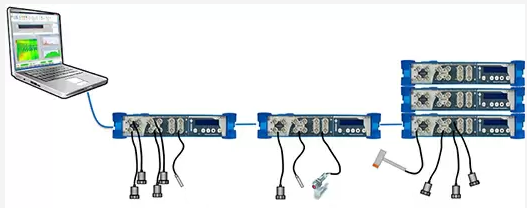
High-precision synchronous measurements (0.2 ° @ 20kHz) are possible by simply connecting each analyzer using a general-purpose LAN cable. Function measurements can be taken with the hammer connected to the third unit in the chain and the accelerometers connected to each unit. Tracking analysis can be completed with the accelerometers connected to each unit while using a tachometer connected to the second unit in the chain.
Measure From Sound / Vibration and Strain Gauge / Temperature
(OR35 / TW OR36 / TW OR38 only)
By mounting a strain gauge conditioner and thermocouple conditioner on the Oros FFT analyzer, it is possible to measure strain and temperature data in addition to sound and vibration data.
Thermocouple amplifier: Supports types J, K, T, N, E (with temperature compensation)
CAN-bus Module Available
(OR10/ TW OR35 / TW OR36 / TW OR38 only)
By using the CAN-bus module, tracking analysis can be performed using information such as the engine speed flowing from the CAN-bus. By using this function, tracking analysis can be performed without using a tachometer.
Recording is possible without the use of a PC by using the FFT analyzer in stand alone mode
(OR35 / TW OR36 / TW OR38 only)
The FFT analyzer is equipped with a record-only button. Simply select a predefined measurement setup and press the record button to record onto the FFT analyzer alone without the use of a PC.
In addition, the back of the Fast Fourier Transform Spectrum Analyzer Multipurpose is equipped with an audio terminal and power supply. It is possible to record audio data while also measuring the time signal. The analyzer also can supply power to required sensors, such as proximity probes, tachometers and DC sensors.
Software Introduction
- Easy-to-use interface
- Real-time measurement / post-analysis can be performed with the same software platform (NVGate)
- One-click report creation function
Start the Measurement Quickly and Easily
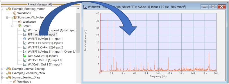
You can start measuring immediately by using the quick function provided in the OROS FFT analyzer mult function. This is completed by defining the number of input channels in the channel field and the measurement/analysis content in the show results area.
The Oros series FFT spectrum analyzer multifunction uses an interface similar to the ribbon interface used by Microsoft Office. All menus are accessible via the ribbon interface, making it easy to change measurement settings.
One-click Setting Function
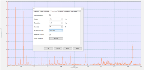
With the Oros series multi-purpose FFT analyzer, you can display related measurement condition settings by double-clicking on the measurement screen. For example, if you double-click on the FFT analysis screen, the dialog for setting the measurement conditions for FFT analysis will be displayed on the screen as shown below.
Control Panel
In addition, the OROS FFT spectrum analyzer is equipped with a control panel function that allows users to save frequently used measurement settings for quick access. By using this function, all settings can be changed on the control panel. For example, the following is the setting screen for a hammer test. By saving the input settings, threshold settings, and FFT analysis settings to the control panel as shown below, it is possible to make all the necessary settings quickly by only using the control panel.
Various filters can be applied to recorded signals & FFT analysis results
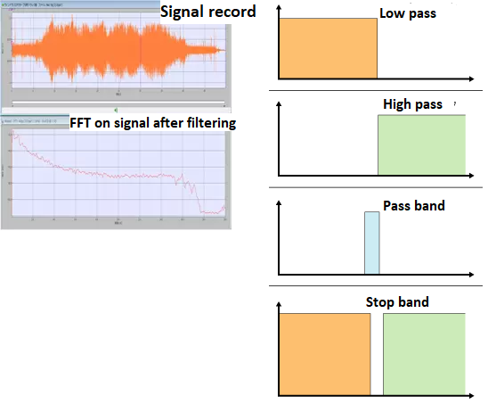
Four types of filters: Low-pass filter, high-pass filter, band-bus filter, and band-stop filter, can be applied to the results of recorded signal and FFT analysis. By using a filter, it is possible to remove abnormal noise components from the recorded signal and perform processing such as reproducing the extracted abnormal noise components.
Extract arbitrary order components from the color spectrum graph in real time
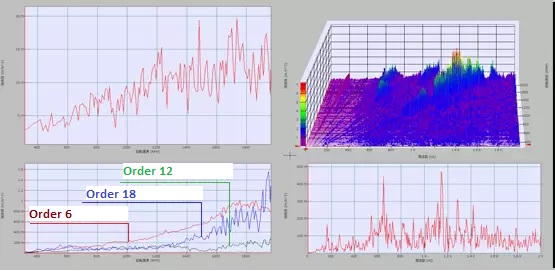
Any order component can be extracted in real time from the color spectrum graph.
Easy-to-read Layout
The area for arranging windows is called a layout. The OROS multi function FFT analyzer can create up to 16 layouts per project. You can easily arrange your windows by using the layout function. And your windows will open the same way each time.
It is possible to display up to 32 screens in one layout.
Up to 512 windows (= 16 x 32) can be displayed.
Layout utilization example:
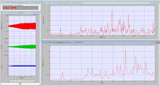
Layout 1: Record waveform, FFT analysis result, order ratio analysis result displayed
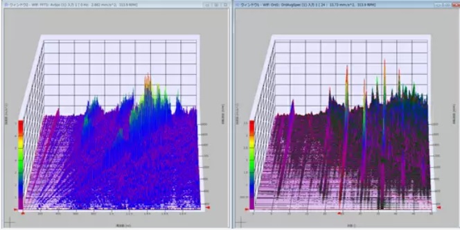
Layout 2: Display 3D frequency analysis results and 3D order ratio analysis results
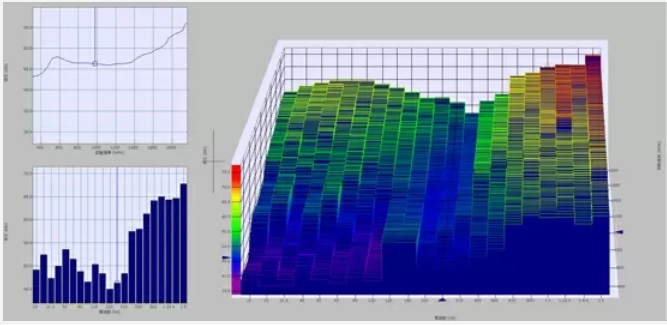
Layout 3: Display 3D octave analyzer analysis results
Easy operation <Graph layout selection button>
You can easily arrange windows just by selecting the grid menu.
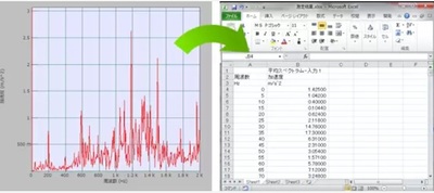
Batch copy of measurement data with one menu. Numerical data can be transferred to Excel all at once.
Data measured at different times can be overwritten by dragging which allows for easily comparing measurement data.
One-click report creation function
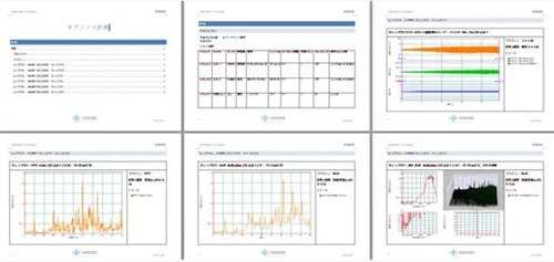
Simply click the report button located on the ribbon interface to create a report file containing the current measurement results.
• The content of the report is customizable. Customize it to the format that best suits your needs.
Measurement data search function
Various information (meta-data) can be added when saving measurement data. You then can search for measurement data and projects based on the added information.
Filter:
- Project name
- Measurement date and time
- Measurement conditions
- Measurement target
- Measurement site
- User
Fail judgment function as standard
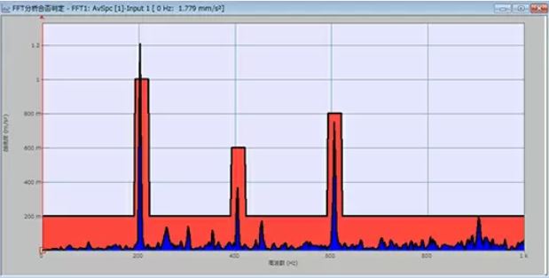
The pass / fail feature of NVGate can be performed automatically after setting the desired bounds.
In the example below, a dialog is displayed when the product fails, but it is also possible to output a contact signal instead of the dialog.
Automate post-analysis processing
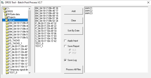
The same processing can be continuously performed for record files measured multiple times. By using this function, it is possible to automate the generation of reports, and it is possible to generate the same number of post-analysis results and EXCEL-based reports as record files with one click. Processing that used to take more than a week can now be done in a few hours.
specification
Main specifications
| O4 | OR10 | OR35 | OR36 | OR38 | |||
|---|---|---|---|---|---|---|---|
| Dynamical Input channel | |||||||
| Number of analysis channels | 2, 4 | 4, 8 | 6, 10 (Select Analysis or tachometer on 2 channels) |
4, 8, 12, 16 | 8, 16, 24, 32 | ||
| Terminal shape | BNC | Lemo (deliverd with "Lemo to BNC" cable) | BNC | ||||
| Input coupling and sensor support | Compatible with AC, DC / ICP (sensor with built-in amplifier) and TEDS | ||||||
| Cutoff frequency | -3dB at AC cutoff frequency 0.35Hz | ||||||
| Input voltage range | +/-: 100mV to +/-: 40V (auto range function) | ||||||
| Maximum voltage | 60V | ||||||
| Anti-Aliasing filter | 400dB / OCT | ||||||
| Input impedance | 1MΩ <100pF | ||||||
| A / D converter | 24-bit | ||||||
| Dynamic range | >140dB | ||||||
| Channels-to-channels phase accuracy | ± 0.02 ° (10V, 20kHz range) | ||||||
| Input filter | Acoustic A, C, Z, low pass, high pass, band pass, integrator, differentiator, time axis integration function | ||||||
| Sampling frequency of the signal | Select from 13 ranges between 102.4kHz and 2.048kHz. | ||||||
| Tachometer channel (Ext synch channels) | |||||||
| Number of input channels | 2 channels | 2 channels (up to 6 channels as an option) | |||||
| Sampling frequency | 6.4MHz (counter method) | ||||||
| Voltage range | +/- 300mV 40V | ||||||
| DC input | |||||||
| number of input channels | none | Analysis channel can be switched and used | |||||
| Voltage range | none | 22 bits, ± 40V, offset DC 100μV or less | |||||
| Samplingfrequency | none | 15Hz or 12.5Hz | |||||
| Calibration function | |||||||
| Calibration method | Automatic sensitivity calculation by numerical input or reference signal (for position and standard vibration oscillatory meter) | ||||||
| How to use at the time of measurement | Select by registered sensor name such as model name and machine number | ||||||
| Trigger function | |||||||
| Trigger type | Edge, period, △ RPM, △ level, manual, multi (A or B, A and B, A after B) | ||||||
| Trigger delay | Pre- and post-trigger functions | ||||||
| Trigger signal | Select from any input channel | ||||||
| Record function | |||||||
| Sampling frequency | 13 ranges from 102.4kHz to 2.048kHz possible to select 2 types of range together | ||||||
| A / D converter resolution | 24-bit or 16-bit | ||||||
| Hard drive size | PC hard drive | 64 GB SSD | 128 GB removable SSD hard drive (256GB or 512 GB optional) | ||||
| FFT analysis performance | |||||||
| Analysis frequency range | 0.8Hz-100kHz | 0.8Hz-40kHz | |||||
| FFT block size | 256, 512, 1024, 2048, 4096, 8192, 1638 | ||||||
| Number of analysis lines | 101, 201, 401, 801, 1601, 3201, 6401 | ||||||
| Zoom analysis | 2 to 128 times (all channels at the same time) | ||||||
| Overlap setting | 0-99.99% | ||||||
| Window function | Flat Top, Hanning, Humming, Kaiser Vessel, Rectangular, Force / Response | ||||||
| Average mode | Time, frequency, fdsa / linear, exponential, peak hold | ||||||
| Analysis / display function | |||||||
| Time series | Real-time waveform, record waveform, DC, Max, Min, RMS | ||||||
| FFT analysis | Linear power spectrum, average spectrum, PSD, cross spectrum,
transfer function (H1, H2), copying function | ||||||
| Display color | Display color: Arbitrary specification of trace, cursor, background, and grid display colors | ||||||
| Options: | |||||||
| Time domain analysis (ORNV-TDA) | |||||||
| Analysis items | Monitor display for arbitrary time (msec to day), effective value for arbitrary section, Min, Max, Peak,
Peak / Peak, RMS, DC, crest factor, Skew, Kurtosis | ||||||
| 1/n octave analysis (ORNV-OCT) | |||||||
| method | Digital filter operation on time domain | ||||||
| Analysis band | 1/1, 1/3, 1/12, 1/24 octave (IEC1260: 1995 Class 1, ANSI S1.11-1986) | ||||||
| Analysis frequency | Simultaneous analysis of all channels at 20kHz is possible (DSP option may be required) | ||||||
| Average | Fast, Slow, lmpulse, LEQ, constantBT, linear repeat,exponential | ||||||
| Multi-sound level meter [ORNV-OVA] | |||||||
| Operation method | Time series signal digital operation | ||||||
| Acoustic weithing | Linear, A, C | ||||||
| Measurement | Leq, Fast, Slow, lmpulse, average, Peak, Max, Min | ||||||
| Average | Fast, Slow, lmpulse, LEQ, constantBT, linear repeat,exponential | ||||||
| Synchronous Order tracking analysis [ORNV-ORD] | |||||||
| Analysis function | Instantaneous and average spectrum,phase, order profile and overall. | ||||||
| Maximum rotation speed | 1,200,000 RPM | ||||||
| Max analysis ordersetting | 6.25, 12.5, 25, 50, 100, 200, 400 | ||||||
| Number of analysis lines | 25-800 | ||||||
| Analysis bandwidth | resampling method and fixed sampling method | ||||||
| display | Simultaneous display of 3D display and tracking order, simultaneous display of time signal | ||||||
| Rotational torsion analysis [ORNV-IVC] | |||||||
| Operation method | Digital Frequnecy Voltage converter | ||||||
| Number of analysis channels | 2ch | 2ch (up to 6ch as an option) | |||||
| Rotation diagnosis function [ORNV-FFTDiag] | |||||||
| Analysis items | Envelope analysis, cepstrum, self-cross function, MAX, MIN, peak detection from block data, simulated tach, | ||||||
| Output Channel | |||||||
| Number of output channels | 1ch (lemo conector, include) | no output | 2ch | 2ch (up to 6ch as an option) | |||
| Output waveform | Sinus, step sinus, sweep sinus, chirp, multi-sinus, random (pink and white), DC voltage, record signal | Sinus, step sinus, sweep sinus, chirp, multi-sinus, random (pink and white), DC voltage, record signal | |||||
| Digital / Analogic converter | 24 bits | 24 bits | |||||
| Output voltage | +/- 10V | +/- 10V | |||||
| Output Inpedence | 50 Ω | 50 Ω | |||||
| Frequency range | ~ 100kHz | ~ 40kHz | |||||
| Sweep mode | Sweep and step, analyze, trigger and sync, linear and log | Sweep and step, analyze, trigger and sync, linear and log | |||||
| Synchronization with the analysis | Synchronization and free run | Synchronization and free run | |||||
| Output protection | Stabilization with time specification and forced stop button | Stabilization with time specification and forced stop buttoz | |||||
| Data | |||||||
| Image and print | Image, printing for Windows and user template creation function for Word and Excel | ||||||
| File | TXT, UFF, MATLAB, WAV (OROS and Audio) SDF, binary, ATFX (optional) | ||||||
| Data entry | WAV, TXT, UFF and OR20 series AE2 | ||||||
| Dimensions / weight | |||||||
| Dimensions (width x height x depth mm) | 35 x 110 x 185 | 37 x 174 x 120 | 56 × 246 × 222 | 102 x 260 x 311 | 102 x 364 x 311 | ||
| Weight | 0.5kg | 0.85kg | 2.8kg | 5.2 kg | 8.2 kg | ||
| Power supply | |||||||
| AC | AC 100V-240V | ||||||
| DC | USB 3.0 type C 5V | USB 15V | 10V-28V, 20VA | 10V-28V, 60VA | 10V-28V, 100VA | ||
| DC battery internal operating time (built-in) | NA : using PC battery | 4h | 3h | 2h | 2h | ||
| Recommended operating temperature range | 0 ℃ ~ 40 ℃ | 0 ℃ ~ 50 ℃ | 0 ℃ ~ 45 ℃ | ||||
| cooling fan | Fan less | Fan less | Automatic control by built-in temperature sensor, forced stop possible (however, forced ON when the temperature rises above 50 ° C) | ||||
PC requirement
| Connections | Type: Ethernet, Connector: RJ45 |
|---|---|
| Operating systems | Windows 7 / Windows 10 / Windows 11 |
| Recommended | CPU : Quad core processor (Desktop : Intel Core i3 or Ryzen 3, Laptop : Intel Core i5 or Ryzen 5) RAM : 6 GB |
Function
Catalog download
Applications/ Case study
Main application and commonly used functions:
FFT analyzers are used in research and development, quality control, inspection, service departments, etc.
Improvements in vehicle quietness, ride quality, comfort, maneuverability, etc.
- Frequency analysis
- 1 / N octave analysis
- Resonance frequency measurement by vibration
- Experimental mode analysis
Responding to quality problems caused by vibration and noise of vehicles and rotating equipment
- Overall measurement
- Frequency analysis
- Turbomachinery Analysis
- Rotation order ratio / RPM tracking analysis
- Rotational torsional vibration analysis
- Resonance frequency measurement by vibration
Environmental problems caused by noise from construction machinery, office machines, home appliances, etc.
Problems with processing accuracy due to minute vibrations in microscopes, machine tools, semiconductor manufacturing equipment, etc.
A collection of application examples using the OROS FFT analyzer OROS series
Introducing solution examples that can be provided by various functions unique to OROS FFT analyzers.
- Vibration measurement of cutting machine
Introducing what approach can be taken using the OROS FFT Analyzer to identify mechanical resonance problems due to changes in cutting conditions.
Download on my.oros.com (need register)
- Monitoring of wind power generation equipment and abnormality diagnosis
Measuring vibration noise generated from rotating machines (gearboxes, generators, etc.) in wind power generation equipment is indispensable for equipment maintenance and longevity. In addition to the real-time analysis capability of rotating machinery, which is the strength of the OROS FFT analyzer, remote control / monitoring and stand-alone functions can be used to more efficiently diagnose equipment for wind power generation equipment.
Download on my.oros.com (need to register)
- Diesel engine camshaft rotational twist measurement
In the prototype of a small diesel engine, there is a problem that the rotational torsional vibration of the timing belt and the camshaft resonates, causing a large vibration. By measuring rotational fluctuations and rotational twists with high accuracy using the six tachometer channels mounted on the OROS FFT analyzer, it is clarified which rotational order is dominant for vibration.
Download on my.oros.com (need register)
- Much more Application note on my.oros.com
Some references:
Full technical support
- Hotline dedicated
Responsiveness is the key to offer the best level of services. OROS relies on a powerful network of subsidiaries, offices, resellers, maintenance centers and qualified partners. They are the first steps of efficiency.
Tel: +33.4.76.90.52.40
Email: customer.care@oros.com
- User training course
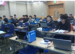
OROS proposes training specially dedicated to customers every year for free (depending on countries). This is an opportunity to take advantage of your analyzer system capabilities, to get premium information on OROS range evolution, to discuss with your peers, and for OROS, to listen to your product enhancement desires.
- Worldwide presence and accredited maintenance center
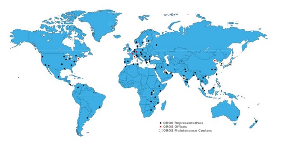
With a worldwide coverage of distributor network and maintenance center (China, Europe, India, Japan, Saudi Arabia, South Korea, USA), OROS is in close proximity to its customers, reducing maintenance downtime.
Find Your local distributor
Technicians are certified on a regular basis by OROS specialists, enabling them to repair, calibrate and upgrade all OROS systems.
- Premium contract
1, 2 or 4 years renewable contracts to extend your warranty.
- Access to the latest software version.
- Full coverage on your instrument (calibration and maintenance)
- Guaranteed turn around time (4 days) for hardware repairs and calibration
- Privileged access to extended services at a preferential rate: urgent loan within 1 day.
Video content
We have released videos such as product introductions and demonstrations.
Click here for the youtube video content page
| Schedule a demo | Get a quotation | Contact support |


