Difference between revisions of "Human Vibration"
(→VDV) |
|||
| Line 179: | Line 179: | ||
If the "VDVTexp" box is checked, an evaluation of the VDV value over a longer time period will be calculated of each channel as : <br><br> | If the "VDVTexp" box is checked, an evaluation of the VDV value over a longer time period will be calculated of each channel as : <br><br> | ||
<math display="block" forcemathmode="5">VDV_{X,Y,Z}(T) = VDV_{i}*k_{X,Y,Z}*\sqrt[4]{\frac{T_m}{T}}</math> <br> | |||
With <math>T_m</math> the duration of the measurement and <math>T</math> the total exposure duration represented by the "Reference time" parameter, and <math>k_{X}=k_{Y}=k_{Z}=1</math> | |||
======MSDV====== | ======MSDV====== | ||
Revision as of 12:07, 2 December 2020
The OROS Body Vibration tool allow you to evaluate the affect of vibration on the human body according to standards ISO 2651 and ISO 5349. These standard define measurement practice and vibration signal analysis to evaluate the affect on health and and comfort of environmental and equipment vibrations on the Human body.
The ISO 2651 describe the affect on health and comfort of vibration on the whole-body in transportation system, and the ISO 5349 the affect on health of vibration on hands and arms when manipulating machine-tools or vibrating objects. In the following, we will see how to use OROS to evaluate these effect.
This is a post analysis toolkit, operating alongside NVGate after the recording of the signal and will help you to calculate time-weighted signal of acceleration and specific indicators both defined in the standards.
Download & install
Download the program here (version from 16/11/2020) : https://orossas.sharepoint.com/:u:/g/support/ERx7p7QyS3tFvwhLyzDk-I8BhYdZULbj1WYLRA4xHJGc7A?e=sdgiBS
Once downloaded, you can unzip the folder and lunch the installer program Setup_OROS_BodyVibration_Tool_vXX.exe. Follow the step of the program to properly install the software.
The program will be installed in "C:\OROS\Programs\ExternalTools". Shortcuts are created on the main desktop, in the Windows Start program and in the "Link" repertory of NVGate. By that way you can directly run the program from NVGate.
How to use
- Launch NVGate
- Launch OROS_BodyVibration_Tool.exe
- Open a project in NVGate
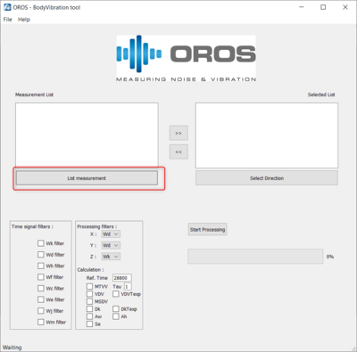
- In the tool, Click on list measurement to list all the measurement present in the project (only the measurement where the signal files are actually on the disk will be displayed. Ensure you have downloaded signal from the OR3X disk)
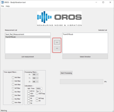
- Add the measurement you want to analyse in the "selected list" area using the ">>" button. Use the "<<" button to remove file if needed.
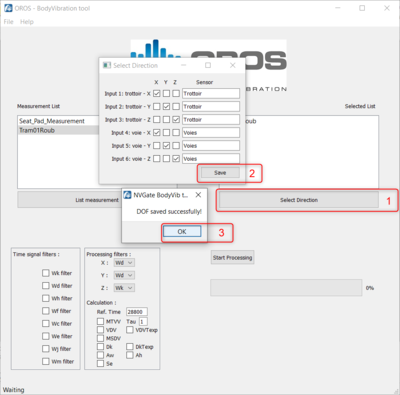
- Click on "Select Directions" to set the direction and sensor for each channel (This step is not necessary if you only want the time-weighted signals).
- Select the weighting you want to apply on the time signal
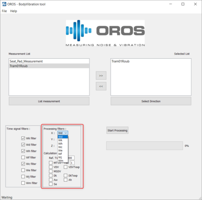
- Select the weighting you want to apply for each direction X, Y and Z used for the indicators
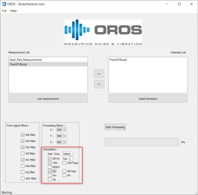
- Select the metrics you want to calculate
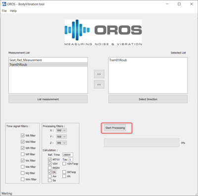
- Click on "Start Processing"
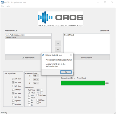
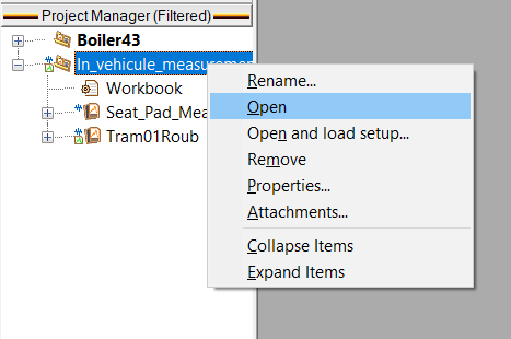
- The processing is completed when a the following pop-up window appear. The results and weighted signal have added to the current NVGate project. See the next sections for details.
Toolkit results
Time-weighted signal
Studies of the affect of vibrations on the human body suggest that part of the body don't have the same response to vibrations, and will be sensitive to specific frequencies and transient component of vibration signal. In order to represent the sensitivity of the human boy, ISO standards defined time-weighting that must applied to the signal according to the environmental conditions. The following part present you how to apply time-weighting filters to your signal using the toolkit.
Time-weighting filters
As defined in the standards, specific time weighting must be applied to the acceleration signal in order to represent the effect of vibrations on health and comfort. Here is the list of the different time-weighting filters implemented in the toolkit :
| Failed to parse (MathML with SVG or PNG fallback (recommended for modern browsers and accessibility tools): Invalid response ("Math extension cannot connect to Restbase.") from server "https://wikimedia.org/api/rest_v1/":): {\displaystyle W_k} | Time weighting for the Z axis for whole-body measurement (ISO 2651-1) |
| Failed to parse (MathML with SVG or PNG fallback (recommended for modern browsers and accessibility tools): Invalid response ("Math extension cannot connect to Restbase.") from server "https://wikimedia.org/api/rest_v1/":): {\displaystyle W_d} | Time weighting for the X and Y axis for whole-body measurement (ISO 2651-1) |
| Failed to parse (MathML with SVG or PNG fallback (recommended for modern browsers and accessibility tools): Invalid response ("Math extension cannot connect to Restbase.") from server "https://wikimedia.org/api/rest_v1/":): {\displaystyle W_h} | Time weighting for the hand-arms measurement in any direction (ISO 5349-1) |
| Time weighting for motion sickness measurement in the vertical direction (ISO 2651-1) | |
| Failed to parse (MathML with SVG or PNG fallback (recommended for modern browsers and accessibility tools): Invalid response ("Math extension cannot connect to Restbase.") from server "https://wikimedia.org/api/rest_v1/":): {\displaystyle W_c} | Time weighting for the X axis for whole-body measurement (ISO 2651-1) |
| Time weighting for all rotational directions for whole-body measurement (ISO 2651-1) | |
| Failed to parse (MathML with SVG or PNG fallback (recommended for modern browsers and accessibility tools): Invalid response ("Math extension cannot connect to Restbase.") from server "https://wikimedia.org/api/rest_v1/":): {\displaystyle W_j} | Time weighting for the Z axis for head comfort measurement (ISO 2651-1) |
| Time weighting for all directions for building's vibration comfort measurement (ISO 2651-2) |
Filters have been validated from 0.5 to 10kHz at 25.6kSample/second.
Usage in the toolkit
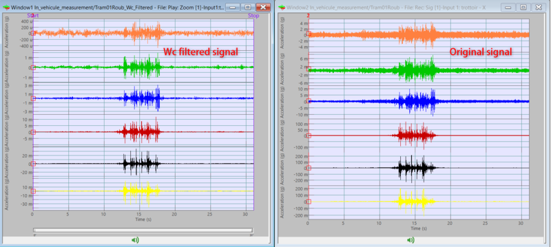
The toolkit allow you to calculate the filtered raw signal with any of the above weighting filters. This will allow you to display spectrums and calculate RMS via post-analysis in NVGate.
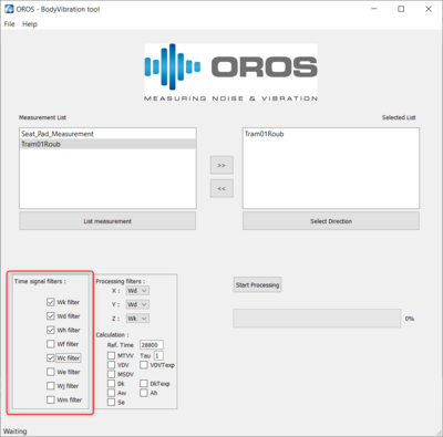
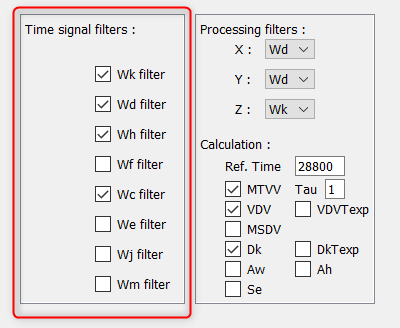
To calculate the raw weighted signal, simply select the filters you want in the "Time signal filters" section :
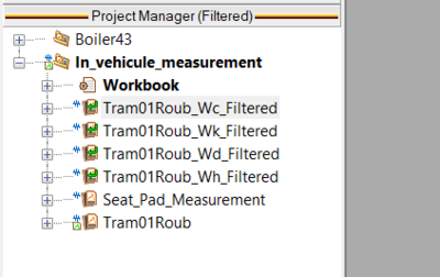
Once the processing is completed, a new measurement containing the filtered signal for each selected filter is created in NVGate Project Manager :
You can then load the new signals in the player as any NVGate signal. Each track of the signal is filtered with the corresponding filter.
Health and comfort indicator
In addition to the time-weighting filters, the ISO standards present a series of specific metrics to evaluate the affect of vibrations on the Human body. The following section will present you how to use the toolkit to access these metrics.
Indicators
| Failed to parse (MathML with SVG or PNG fallback (recommended for modern browsers and accessibility tools): Invalid response ("Math extension cannot connect to Restbase.") from server "https://wikimedia.org/api/rest_v1/":): {\displaystyle A_w} | RMS of the weighted acceleration magnitude. |
| Failed to parse (MathML with SVG or PNG fallback (recommended for modern browsers and accessibility tools): Invalid response ("Math extension cannot connect to Restbase.") from server "https://wikimedia.org/api/rest_v1/":): {\displaystyle a_v} | Total RMS value calculated as a quadratic average of the three direction for each tri-axial sensor. |
| Failed to parse (MathML with SVG or PNG fallback (recommended for modern browsers and accessibility tools): Invalid response ("Math extension cannot connect to Restbase.") from server "https://wikimedia.org/api/rest_v1/":): {\displaystyle A_h} | RMS of the Failed to parse (MathML with SVG or PNG fallback (recommended for modern browsers and accessibility tools): Invalid response ("Math extension cannot connect to Restbase.") from server "https://wikimedia.org/api/rest_v1/":): {\displaystyle W_h} weighted acceleration magnitude. |
| Failed to parse (MathML with SVG or PNG fallback (recommended for modern browsers and accessibility tools): Invalid response ("Math extension cannot connect to Restbase.") from server "https://wikimedia.org/api/rest_v1/":): {\displaystyle Peak} | Amplitude Peak of the vibration; maximal amplitude of the signal from the 0 (Calculated from Post processing in NVGate) |
| Failed to parse (MathML with SVG or PNG fallback (recommended for modern browsers and accessibility tools): Invalid response ("Math extension cannot connect to Restbase.") from server "https://wikimedia.org/api/rest_v1/":): {\displaystyle Crest factor} | Ratio between the Peak level and the RMS of the weighted signal(Calculated from Post processing in NVGate) |
| Failed to parse (MathML with SVG or PNG fallback (recommended for modern browsers and accessibility tools): Invalid response ("Math extension cannot connect to Restbase.") from server "https://wikimedia.org/api/rest_v1/":): {\displaystyle MTVV} | Maximum Transient Vibration Value, represent the maximal RMS value of the signal |
| Failed to parse (MathML with SVG or PNG fallback (recommended for modern browsers and accessibility tools): Invalid response ("Math extension cannot connect to Restbase.") from server "https://wikimedia.org/api/rest_v1/":): {\displaystyle VDV} | Vibration Dose Value, taking into account the temporal shocks in the signal |
| Failed to parse (MathML with SVG or PNG fallback (recommended for modern browsers and accessibility tools): Invalid response ("Math extension cannot connect to Restbase.") from server "https://wikimedia.org/api/rest_v1/":): {\displaystyle MSDV} | Motion Sickness Dose Value, representing the comfort in transportation measurement |
| Failed to parse (MathML with SVG or PNG fallback (recommended for modern browsers and accessibility tools): Invalid response ("Math extension cannot connect to Restbase.") from server "https://wikimedia.org/api/rest_v1/":): {\displaystyle D_k} | The Acceleration Dose, representing the affect of the vibration on the spine |
| Failed to parse (MathML with SVG or PNG fallback (recommended for modern browsers and accessibility tools): Invalid response ("Math extension cannot connect to Restbase.") from server "https://wikimedia.org/api/rest_v1/":): {\displaystyle Se} | The equivalent Static compression stress on the spine, caused by repeated shocks |
Aw
The Failed to parse (MathML with SVG or PNG fallback (recommended for modern browsers and accessibility tools): Invalid response ("Math extension cannot connect to Restbase.") from server "https://wikimedia.org/api/rest_v1/":): {\displaystyle A_w}
is the RMS of the weighted acceleration signal. The weighting is applied in accordance with the direction set for each channel and the weighting filter defined for the direction.
For each channel, the Failed to parse (MathML with SVG or PNG fallback (recommended for modern browsers and accessibility tools): Invalid response ("Math extension cannot connect to Restbase.") from server "https://wikimedia.org/api/rest_v1/":): {\displaystyle A_w}
and Failed to parse (MathML with SVG or PNG fallback (recommended for modern browsers and accessibility tools): Invalid response ("Math extension cannot connect to Restbase.") from server "https://wikimedia.org/api/rest_v1/":): {\displaystyle A_w(T)}
will be calculated. The Failed to parse (MathML with SVG or PNG fallback (recommended for modern browsers and accessibility tools): Invalid response ("Math extension cannot connect to Restbase.") from server "https://wikimedia.org/api/rest_v1/":): {\displaystyle A_w(T)}
is the Daily exposure value, defined as :
Failed to parse (MathML with SVG or PNG fallback (recommended for modern browsers and accessibility tools): Invalid response ("Math extension cannot connect to Restbase.") from server "https://wikimedia.org/api/rest_v1/":): {\displaystyle A_w(T) = A_w*k_{i}*\sqrt{\frac{T_m}{T}}}
With Failed to parse (MathML with SVG or PNG fallback (recommended for modern browsers and accessibility tools): Invalid response ("Math extension cannot connect to Restbase.") from server "https://wikimedia.org/api/rest_v1/":): {\displaystyle T_m}
the duration of the measurement and Failed to parse (MathML with SVG or PNG fallback (recommended for modern browsers and accessibility tools): Invalid response ("Math extension cannot connect to Restbase.") from server "https://wikimedia.org/api/rest_v1/":): {\displaystyle T}
the total exposure duration represented by the "Reference time" parameter. the Failed to parse (MathML with SVG or PNG fallback (recommended for modern browsers and accessibility tools): Invalid response ("Math extension cannot connect to Restbase.") from server "https://wikimedia.org/api/rest_v1/":): {\displaystyle k_i}
factor is defined in the ISO 2631 as Failed to parse (MathML with SVG or PNG fallback (recommended for modern browsers and accessibility tools): Invalid response ("Math extension cannot connect to Restbase.") from server "https://wikimedia.org/api/rest_v1/":): {\displaystyle k_X = k_Y = 1.4}
and Failed to parse (MathML with SVG or PNG fallback (recommended for modern browsers and accessibility tools): Invalid response ("Math extension cannot connect to Restbase.") from server "https://wikimedia.org/api/rest_v1/":): {\displaystyle k_Z = 1}
.
When comparing result from one measurement point in the three direction, the maximum of the Daily exposure value must be used as the total daily exposure value at that point :
Failed to parse (MathML with SVG or PNG fallback (recommended for modern browsers and accessibility tools): Invalid response ("Math extension cannot connect to Restbase.") from server "https://wikimedia.org/api/rest_v1/":): {\displaystyle A_w(T) = max(A_{wX}(T), A_{wY}(T), A_{wZ}(T)) }
av
The Failed to parse (MathML with SVG or PNG fallback (recommended for modern browsers and accessibility tools): Invalid response ("Math extension cannot connect to Restbase.") from server "https://wikimedia.org/api/rest_v1/":): {\displaystyle a_v} is the total RMS vibration value of the weighted acceleration signal. This value will only be calculated if a sensor have been defined in the definition of direction window.
For each tri-axial sensor, the Failed to parse (MathML with SVG or PNG fallback (recommended for modern browsers and accessibility tools): Invalid response ("Math extension cannot connect to Restbase.") from server "https://wikimedia.org/api/rest_v1/":): {\displaystyle a_v}
will be calculated as a quadratic average of the weighted RMS value in the three directions :
Failed to parse (MathML with SVG or PNG fallback (recommended for modern browsers and accessibility tools): Invalid response ("Math extension cannot connect to Restbase.") from server "https://wikimedia.org/api/rest_v1/":): {\displaystyle a_v = \sqrt{{a_{vX}}^{2}*{k_{X}}^{2} + {a_{vY}}^{2}*{k_{Y}}^{2} + {a_{vZ}}^{2}*{k_{Z}}^{2}}}
With Failed to parse (MathML with SVG or PNG fallback (recommended for modern browsers and accessibility tools): Invalid response ("Math extension cannot connect to Restbase.") from server "https://wikimedia.org/api/rest_v1/":): {\displaystyle k_{X,Y,Z}}
a factor defined in the ISO 2631 as Failed to parse (MathML with SVG or PNG fallback (recommended for modern browsers and accessibility tools): Invalid response ("Math extension cannot connect to Restbase.") from server "https://wikimedia.org/api/rest_v1/":): {\displaystyle k_{X}=k_{Y}=1.4}
and Failed to parse (MathML with SVG or PNG fallback (recommended for modern browsers and accessibility tools): Invalid response ("Math extension cannot connect to Restbase.") from server "https://wikimedia.org/api/rest_v1/":): {\displaystyle k_{Z}=1}
Ah
The Failed to parse (MathML with SVG or PNG fallback (recommended for modern browsers and accessibility tools): Invalid response ("Math extension cannot connect to Restbase.") from server "https://wikimedia.org/api/rest_v1/":): {\displaystyle A_h}
is the RMS of the Failed to parse (MathML with SVG or PNG fallback (recommended for modern browsers and accessibility tools): Invalid response ("Math extension cannot connect to Restbase.") from server "https://wikimedia.org/api/rest_v1/":): {\displaystyle W_h}
weighted acceleration signal for hand-arms vibration measurement. For each channel, the Failed to parse (MathML with SVG or PNG fallback (recommended for modern browsers and accessibility tools): Invalid response ("Math extension cannot connect to Restbase.") from server "https://wikimedia.org/api/rest_v1/":): {\displaystyle A_h}
and Failed to parse (MathML with SVG or PNG fallback (recommended for modern browsers and accessibility tools): Invalid response ("Math extension cannot connect to Restbase.") from server "https://wikimedia.org/api/rest_v1/":): {\displaystyle A_h(T)}
will be calculated. The Failed to parse (MathML with SVG or PNG fallback (recommended for modern browsers and accessibility tools): Invalid response ("Math extension cannot connect to Restbase.") from server "https://wikimedia.org/api/rest_v1/":): {\displaystyle A_h(T)}
is the Daily exposure value, defined as :
Failed to parse (MathML with SVG or PNG fallback (recommended for modern browsers and accessibility tools): Invalid response ("Math extension cannot connect to Restbase.") from server "https://wikimedia.org/api/rest_v1/":): {\displaystyle A_h(T) = A_h*\sqrt{\frac{T_m}{T}}}
With Failed to parse (MathML with SVG or PNG fallback (recommended for modern browsers and accessibility tools): Invalid response ("Math extension cannot connect to Restbase.") from server "https://wikimedia.org/api/rest_v1/":): {\displaystyle T_m}
the duration of the measurement and Failed to parse (MathML with SVG or PNG fallback (recommended for modern browsers and accessibility tools): Invalid response ("Math extension cannot connect to Restbase.") from server "https://wikimedia.org/api/rest_v1/":): {\displaystyle T}
the total exposure duration represented by the "Reference time" parameter.
If any sensor is defined, the total Failed to parse (MathML with SVG or PNG fallback (recommended for modern browsers and accessibility tools): Invalid response ("Math extension cannot connect to Restbase.") from server "https://wikimedia.org/api/rest_v1/":): {\displaystyle A_h}
and Failed to parse (MathML with SVG or PNG fallback (recommended for modern browsers and accessibility tools): Invalid response ("Math extension cannot connect to Restbase.") from server "https://wikimedia.org/api/rest_v1/":): {\displaystyle A_h(T)}
will be calculated for each sensor as a quadratic average of the three direction of the sensor :
Failed to parse (MathML with SVG or PNG fallback (recommended for modern browsers and accessibility tools): Invalid response ("Math extension cannot connect to Restbase.") from server "https://wikimedia.org/api/rest_v1/":): {\displaystyle A_{h Total} = \sqrt{{a_{hX}}^{2}*{k_{X}}^{2} + {a_{hY}}^{2}*{k_{Y}}^{2} + {a_{hZ}}^{2}*{k_{Z}}^{2}}}
and :
Failed to parse (MathML with SVG or PNG fallback (recommended for modern browsers and accessibility tools): Invalid response ("Math extension cannot connect to Restbase.") from server "https://wikimedia.org/api/rest_v1/":): {\displaystyle A_{h Total}(T) = \sqrt{{a_{hX}}^{2}*{k_{X}}^{2} + {a_{hY}}^{2}*{k_{Y}}^{2} + {a_{hZ}}^{2}*{k_{Z}}^{2}}*\sqrt{\frac{T_m}{T}}}
With Failed to parse (MathML with SVG or PNG fallback (recommended for modern browsers and accessibility tools): Invalid response ("Math extension cannot connect to Restbase.") from server "https://wikimedia.org/api/rest_v1/":): {\displaystyle T_m}
the duration of the measurement and Failed to parse (MathML with SVG or PNG fallback (recommended for modern browsers and accessibility tools): Invalid response ("Math extension cannot connect to Restbase.") from server "https://wikimedia.org/api/rest_v1/":): {\displaystyle T}
the total exposure duration represented by the "Reference time" parameter, and Failed to parse (MathML with SVG or PNG fallback (recommended for modern browsers and accessibility tools): Invalid response ("Math extension cannot connect to Restbase.") from server "https://wikimedia.org/api/rest_v1/":): {\displaystyle k_{X}=k_{Y}=k_{Z}=1}
Peak
This indicator is the peak amplitude of the vibration signal. It represent the maximal amplitude of the weighted signal. This indicator can be obtained in NVGate by post-analysing the weighted signal with the TDA plugin of NVGate.
MTVV
The MTVV is the Maximal Transient Vibration Value, is the maximum of the running RMS of the weighted acceleration. This value is calculated for each channel and is expressed in m/s².
The MTVV Tau is the integration time, expressed in seconds. This value can be edited before the calculation, but the ISO 2631 recommand to use 1 second. Therefore this is the default value of this parameter.
VDV
The VDV is the forth power Vibration Dose Value. It is calculated as a cumulative sum of the weighted acceleration at the forth power. The forth power is used to give more weight to the transient event of the signal over the periodic event. Therefore, this indicator must be used to asses the effect of shock on human health and comfort. The VDV is calculated for each channel and expressed in m/s^(1.75).
If the "VDVTexp" box is checked, an evaluation of the VDV value over a longer time period will be calculated of each channel as :
Failed to parse (MathML with SVG or PNG fallback (recommended for modern browsers and accessibility tools): Invalid response ("Math extension cannot connect to Restbase.") from server "https://wikimedia.org/api/rest_v1/":): {\displaystyle VDV_{X,Y,Z}(T) = VDV_{i}*k_{X,Y,Z}*\sqrt[4]{\frac{T_m}{T}}}
With Failed to parse (MathML with SVG or PNG fallback (recommended for modern browsers and accessibility tools): Invalid response ("Math extension cannot connect to Restbase.") from server "https://wikimedia.org/api/rest_v1/":): {\displaystyle T_m} the duration of the measurement and Failed to parse (MathML with SVG or PNG fallback (recommended for modern browsers and accessibility tools): Invalid response ("Math extension cannot connect to Restbase.") from server "https://wikimedia.org/api/rest_v1/":): {\displaystyle T} the total exposure duration represented by the "Reference time" parameter, and Failed to parse (MathML with SVG or PNG fallback (recommended for modern browsers and accessibility tools): Invalid response ("Math extension cannot connect to Restbase.") from server "https://wikimedia.org/api/rest_v1/":): {\displaystyle k_{X}=k_{Y}=k_{Z}=1}
MSDV
Dk
Se
In the toolkit
Before calculating the indicators in the toolkit, you must define a filter for each directions. Filters will be selected in accordance with the wanted result (Hand-arms; Whole-Body, ..) and the direction of the measurement as specified in the table describing the filters. Filters will be applied to the signal before calculating the indicators, but the time-filtered signal will not be saved.
File:Processing Filter.png
You will then need to select the indicators to be calculated bi ticking the boxes.
File:Selected Processing.png
The MTVV Tau is the integration time in seconds used for the calculation of the MTVV. The ISO 2651 recommand to use 1sec. This is the default value of the setting.
You can then start the processing to calculate the indicators.
Once completed, the result can be find the currently opened project in the NVGate Project manager. A new measurement called "NAME_OF_THE_Signal_out" containing the result is created. As many measurement folder as selected signal will be created during the processing.
File:Project Manager results.png
Each indicator is calculated for each direction and for each track of the signal. The name of the result contain the name of the track, the considered direction and the filter used for that direction (except for the Failed to parse (MathML with SVG or PNG fallback (recommended for modern browsers and accessibility tools): Invalid response ("Math extension cannot connect to Restbase.") from server "https://wikimedia.org/api/rest_v1/":): {\displaystyle D_k}
which use specific filters). The following picture show the indicators for the first track (SeatPadX) of the signal :
File:Result for track.png
Here this track represent the X direction. We can remove the results in irrelevant directions (Y and Z) for this track by a right click, and repeat this operation for each channel :
/Insert image of the result with only relevant direction when bug solve/
You can then display the result in NVGate by double clicking.
Calculating the other indicators with NVGate
Failed to parse (MathML with SVG or PNG fallback (recommended for modern browsers and accessibility tools): Invalid response ("Math extension cannot connect to Restbase.") from server "https://wikimedia.org/api/rest_v1/":): {\displaystyle A_w}
Failed to parse (MathML with SVG or PNG fallback (recommended for modern browsers and accessibility tools): Invalid response ("Math extension cannot connect to Restbase.") from server "https://wikimedia.org/api/rest_v1/":): {\displaystyle A_w} is the daily vibration dose. It is calculated from an average of the RMS values form the weighted signal and represent the "quantity" of vibration the human body will receive when using of the tested equipment.
This value is defined as : Failed to parse (MathML with SVG or PNG fallback (recommended for modern browsers and accessibility tools): Invalid response ("Math extension cannot connect to Restbase.") from server "https://wikimedia.org/api/rest_v1/":): {\displaystyle A_w = \sqrt{(k_{x}*a_{w_{x}})^2+(k_{y}*a_{w_{y}})^2+(k_{z}*a_{w_{z}})^2}}
, with Failed to parse (MathML with SVG or PNG fallback (recommended for modern browsers and accessibility tools): Invalid response ("Math extension cannot connect to Restbase.") from server "https://wikimedia.org/api/rest_v1/":): {\displaystyle k_i}
defined in the standard and Failed to parse (MathML with SVG or PNG fallback (recommended for modern browsers and accessibility tools): Invalid response ("Math extension cannot connect to Restbase.") from server "https://wikimedia.org/api/rest_v1/":): {\displaystyle a_{w_{x}}}
the RMS value of the weighted acceleration signal in accordance to the direction, as defined in the table of the precedent section.
Calculation in NVGate
To calculate the Failed to parse (MathML with SVG or PNG fallback (recommended for modern browsers and accessibility tools): Invalid response ("Math extension cannot connect to Restbase.") from server "https://wikimedia.org/api/rest_v1/":): {\displaystyle A_w}
in NVGate, calculmate the RMS level of the weighted signal in Post analysis. Here, we will calculate the Failed to parse (MathML with SVG or PNG fallback (recommended for modern browsers and accessibility tools): Invalid response ("Math extension cannot connect to Restbase.") from server "https://wikimedia.org/api/rest_v1/":): {\displaystyle A_w}
for the SeatPad measurement as defined for a whole-body measurement in the ISO 2651. According to the [Human_Vibration#Time-weighting_filters|table]], we need to calculate the RMS level of the Failed to parse (MathML with SVG or PNG fallback (recommended for modern browsers and accessibility tools): Invalid response ("Math extension cannot connect to Restbase.") from server "https://wikimedia.org/api/rest_v1/":): {\displaystyle W_k}
weighted signal for the Z direction and the Failed to parse (MathML with SVG or PNG fallback (recommended for modern browsers and accessibility tools): Invalid response ("Math extension cannot connect to Restbase.") from server "https://wikimedia.org/api/rest_v1/":): {\displaystyle W_d}
weighted signal for the X and Y directions. You then must display the three RMS level in the same window :
Ah and Ah(8)
VDV Texp
Practical information about measurements
Durée de mesure Type de mesure Placement des capteurs Exemple de capteur : [Pad accelerometer] Capteur avec adaptateurs hand arms
