Difference between revisions of "MultiPlane Balancing"
| (21 intermediate revisions by 2 users not shown) | |||
| Line 1: | Line 1: | ||
<big>This software is now depreciated.</big> | |||
The new version (easier to use) include single dual and multiplane. Please contact us for having avvess to this version. | |||
==Multiplane balancing:== | |||
[[ | {{Software | ||
|Logo= [[image:rotating-T-256.png|90px]] | |||
|Name= Multiplane Balancing | |||
|Screenshot=[[File:MULTIPLANE_BALANCING_26.png|120px]] | |||
|Developers= [http://www.OROS.com Oros SA] | |||
|Type= [https://en.wikipedia.org/wiki/Balancing_of_rotating_masses Balancing of rotating masses], [https://en.wikipedia.org/wiki/Signal_processing Signal processing],Industrial Rotating machines, [https://en.wikipedia.org/wiki/Vibration Vibration], | |||
|First release= 2012 | |||
|Latest Version= V2.57 | |||
|Download= [[MultiPlane_Balancing|Here]] | |||
|Update= | |||
|Operating system= Windows 10 (and W7) ([[PC_Requirements|see PC requirements]]) | |||
|Language= English, German, French | |||
|Licence = Proprietery | |||
|website=[https://www.oros.com/solutions/rotating-analysis/balancing/ Balancing on oros.com] and here! | |||
}} | |||
[[MultiPlane_Balancing_Install|Install]]<br> | |||
[[MultiPlane_Balancing|Manual]]<br> | |||
[[MultiPlane_export_1X_NVGate|How to set up NVGate for Multi-Plane Balancing]] | |||
[[MultiPlane_Balancing#Exporting_data_from_ORBIGate_to_CSV|How to export data from ORBIGate]] | |||
==Starting up the multiplane balancing module== | ==Starting up the multiplane balancing module== | ||
Plug your | Plug in your license dongle: the dongle license should have been updated to allow the software. The software can be started from the start menu in two ways as follows: | ||
[[Image:MULTIPLANE_BALANCING_07.gif|framed|none]] | [[Image:MULTIPLANE_BALANCING_07.gif|framed|none]] | ||
| Line 75: | Line 75: | ||
====Examples insertion==== | ====Examples insertion==== | ||
In the windows explorer, copy the directory «3Planesexample» and the "CSV example" from the "Examples" directory to the defined project base: for example "Bal data" if it was defined to be so. | |||
====Getting further==== | ====Getting further==== | ||
| Line 99: | Line 99: | ||
====Planes and runs==== | ====Planes and runs==== | ||
The number of runs required depends of the number of balancing planes on which one want to balance the rotor | The number of runs required depends of the number of balancing planes on which one want to balance the rotor. | ||
[[Image:MULTIPLANE_BALANCING_13.png|framed|none]] | [[Image:MULTIPLANE_BALANCING_13.png|framed|none]] | ||
| Line 110: | Line 110: | ||
====Measurement points and channels==== | ====Measurement points and channels==== | ||
A measurement point, connected to an instrument | A measurement point, connected to an instrument channel, is not necessarily linked to a correction plane. Vibration is measured at a bearing. There is not always the same number of channels as the number of planes. Nevertheless there should be enough channels to solve the problem. It is recommended to have at least one channel per balancing plane or relatively close to it. | ||
[[Image:MULTIPLANE_BALANCING_14.png|framed|none]] | [[Image:MULTIPLANE_BALANCING_14.png|framed|none]] | ||
| Line 119: | Line 119: | ||
* The software works in the office mode and is based on 1X data (amplitude and phase) versus RPM. The user will be able to select one or several speed ranges to be balanced. | * The software works in the office mode and is based on 1X data (amplitude and phase) versus RPM. The user will be able to select one or several speed ranges to be balanced. | ||
* Data can be collected with OROS ORBIGate and exported as CSV files with the option" group by results". One can look at the CSV files example provided with the installation. | * Data can be collected with OROS ORBIGate and exported as CSV files with the option" group by results". One can look at the CSV files example provided with the installation. | ||
* | * The main steps are: | ||
* Rotor configuration and trial masses positions | ** Rotor configuration and trial masses positions | ||
* Importing and selecting data (channels selection) | ** Importing and selecting data (channels selection) | ||
* Selecting the RPM range | ** Selecting the RPM range | ||
* Processing the calculations | ** Processing the calculations | ||
* Considering the correction weights and choosing the mounted masses | ** Considering the correction weights and choosing the mounted masses | ||
===The configuration wizard=== | ===The configuration wizard=== | ||
The main configuration wizard contains 5 main steps: | The main configuration wizard contains 5 main steps: | ||
| Line 186: | Line 187: | ||
==Getting started with the Multiplane balancing module== | ==Getting started with the Multiplane balancing module== | ||
This chapter | This chapter shows how to go through each step of the configuration easily and rapidly. In order to get more information on each step refer to chapter 3. | ||
===Starting the software module=== | ===Starting the software module=== | ||
| Line 236: | Line 237: | ||
The data can be displayed in several ways: | The data can be displayed in several ways: | ||
* For each | * For each channel (active or not) | ||
* For each run | * For each run | ||
* In different display types (Magnitude, Phase, Polar, RPM) | * In different display types (Magnitude, Phase, Polar, RPM) | ||
| Line 249: | Line 250: | ||
===Balancing weights=== | ===Balancing weights=== | ||
The balancing weights window is the where the correction weights recommendations are displayed. | |||
[[Image:MULTIPLANE_BALANCING_27.png|framed|none]] | [[Image:MULTIPLANE_BALANCING_27.png|framed|none]] | ||
| Line 277: | Line 278: | ||
Positions are the places where one can put tests masses as well as correction masses on the rotor planes. One should enter the number of positions: they will be distributed evenly around the plane. | Positions are the places where one can put tests masses as well as correction masses on the rotor planes. One should enter the number of positions: they will be distributed evenly around the plane. | ||
Then, one can configure each plane: | Then, one can configure each plane: test masses positions radius, and balancing radius for the positions. | ||
[[Image:MULTIPLANE_BALANCING_30.gif|framed|none]] | [[Image:MULTIPLANE_BALANCING_30.gif|framed|none]] | ||
| Line 283: | Line 284: | ||
''Rotor set-up'' | ''Rotor set-up'' | ||
There are two ways to enter the masses. One | There are two ways to enter the masses. One is to enter them in the table, the other is to enter them in the cells called "Weight" and "Angle". The angle should be an existing one. Otherwise a message will be issued saying that it is not possible. | ||
====Overview==== | ====Overview==== | ||
Clicking on the "Overview" button | Clicking on the "Overview" button allows the user to display where the masses will be positioned on the balancing planes for each run. | ||
[[Image:MULTIPLANE_BALANCING_31.png|framed|none]] | [[Image:MULTIPLANE_BALANCING_31.png|framed|none]] | ||
| Line 293: | Line 294: | ||
====Method of balancing: Remove or Keep the test mass==== | ====Method of balancing: Remove or Keep the test mass==== | ||
There are two possibilities concerning the method to be used. | There are two possibilities concerning the method to be used. The test mass can either be removed or remain. In most cases the test masse is removed, however, sometimes there is no possibility to do that such as situations where the test mass must be welded. | ||
===X data selection=== | ===X data selection=== | ||
| Line 308: | Line 309: | ||
====Importing data==== | ====Importing data==== | ||
=====Exporting data from ORBIGate to CSV===== | =====Exporting data from ORBIGate to CSV===== | ||
One should load a measurement file in the navigation mode of ORBIGate. Then proceed as follows: | |||
Step 1: File/export. | Step 1: File/export. | ||
| Line 323: | Line 324: | ||
=====Importing data from CSV to Balancing===== | =====Importing data from CSV to Balancing===== | ||
Importing data will convert CSV files to ODR files. The first step is to select CSV files from a directory. It should be displayed as in the window below. One can decide to select either (RMS) value or (Pk-Pk) values. Once the files are selected, | Importing data will convert CSV files to ODR files. The first step is to select CSV files from a directory. It should be displayed as in the window below. One can decide to select either (RMS) value or (Pk-Pk) values. Once the files are selected, press "convert and save". It will convert data to ODR files that are able to be used by the software. | ||
[[Image:MULTIPLANE_BALANCING_34.png|framed|none]] | [[Image:MULTIPLANE_BALANCING_34.png|framed|none]] | ||
| Line 333: | Line 334: | ||
* One should not import a file that contains both a run-up and a run-down. | * One should not import a file that contains both a run-up and a run-down. | ||
* One should import data that contain data with the same physical dimension (acceleration, velocity or displacement). | * One should import data that contain data with the same physical dimension (acceleration, velocity or displacement). | ||
====Channels selection==== | ====Channels selection==== | ||
Measurement files contain a number of channels. One doesn<nowiki>'</nowiki>t need to use all the channels. It is possible to make them active (X) or not, by clicking in the cell. | Measurement files contain a number of channels. One doesn<nowiki>'</nowiki>t need to use all the channels. It is possible to make them active (X) or not, by clicking in the cell. This is how they can be selected to be used or not for the calculations. | ||
[[Image:MULTIPLANE_BALANCING_35.gif|framed|none]] | [[Image:MULTIPLANE_BALANCING_35.gif|framed|none]] | ||
| Line 360: | Line 362: | ||
====Runs display==== | ====Runs display==== | ||
* As shown in the following window, one can select the data that should be displayed: | * As shown in the following window, one can select the data that should be displayed: | ||
* For each channels (active or not) | ** For each channels (active or not) | ||
* For each run | ** For each run | ||
* In different display types (Magnitude, Phase, Polar, RPM) | ** In different display types (Magnitude, Phase, Polar, RPM) | ||
[[Image:MULTIPLANE_BALANCING_01.png|framed|none]] | [[Image:MULTIPLANE_BALANCING_01.png|framed|none]] | ||
| Line 371: | Line 373: | ||
====RPM selection==== | ====RPM selection==== | ||
One of the major steps is to select the RPM range for the balancing. It is recommended not to select the critical speed itself as part of the RPM range. At this speed, the phase is changing a lot and it would not provide a good result. Typically, one should keep | One of the major steps is to select the RPM range for the balancing. It is recommended not to select the critical speed itself as part of the RPM range. At this speed, the phase is changing a lot and it would not provide a good result. Typically, one should keep a 100 rpm distance from the peak during the RPM selection. | ||
There are two ways to select the rpm range to be selected: graphical and manual. | There are two ways to select the rpm range to be selected: graphical and manual. | ||
| Line 412: | Line 414: | ||
====Overview==== | ====Overview==== | ||
The overview button | The overview button allows the user to access an overview picture of the correction recommendations for all planes. | ||
[[Image:MULTIPLANE_BALANCING_45.png|framed|none]] | [[Image:MULTIPLANE_BALANCING_45.png|framed|none]] | ||
| Line 421: | Line 423: | ||
====Prognostics==== | ====Prognostics==== | ||
The prognostics | The prognostics is the vibration that can be expected at the selected channel. The prognostics are given as a function of the masses that are chosen to be mounted. The values should be entered in the cell "Mounted weights". | ||
[[File:pronosis.png|framed|none]] | [[File:pronosis.png|framed|none]] | ||
Latest revision as of 09:26, 3 February 2023
This software is now depreciated.
The new version (easier to use) include single dual and multiplane. Please contact us for having avvess to this version.
Multiplane balancing:
| Multiplane Balancing | |
|---|---|

|

|
| Developer | Oros SA |
| Type | Balancing of rotating masses, Signal processing,Industrial Rotating machines, Vibration, |
| First release | 2012 |
| Latest Version | V2.57 |
| Download | Here |
| Operating system: | Windows 10 (and W7) (see PC requirements) |
| Language | English, German, French |
| Official website | Balancing on oros.com and here! |
How to set up NVGate for Multi-Plane Balancing
How to export data from ORBIGate
Starting up the multiplane balancing module
Plug in your license dongle: the dongle license should have been updated to allow the software. The software can be started from the start menu in two ways as follows:
Software start from the Start Menu
The software can be started from the OROS NVSolutions group in the start menu.
Software start from the OROS NVSolutions
Welcome screen
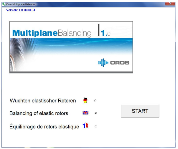
Start the software. The following screen will appear.
Welcome screen and language selection
Choose the appropriate language and press START.
Project base creation
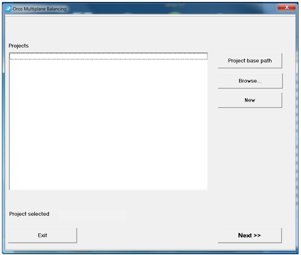
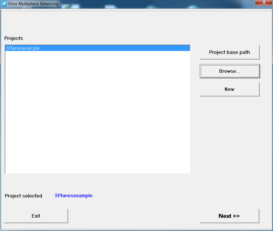
The project window appears:
The project window
At that stage a new project base should be created. Click on "project base path".
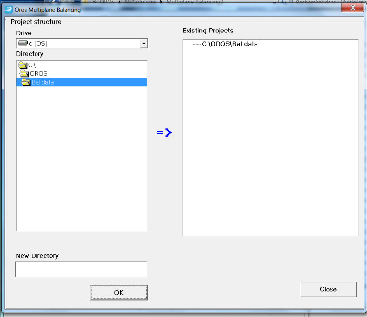
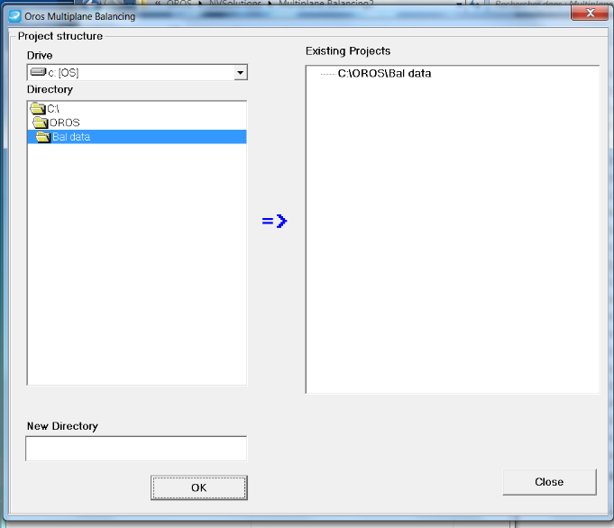
The "project base path" window appears. An available area should be selected on the disk of the user: for example "C:\OROS". Then, a new directory should be created: for example "Bal data".
Creating a new project base
Then you can exit the software. First press "Close" and then "Exit" in the project window.
Examples insertion
In the windows explorer, copy the directory «3Planesexample» and the "CSV example" from the "Examples" directory to the defined project base: for example "Bal data" if it was defined to be so.
Getting further
Then, the software should be started as described above (Chapter 2 of that manual). Refer to the "Multiplane balancing operating manual" for the detailed use of the software by selecting "Help" in the software menus. The "Getting Started" section should be read and followed in order to optimize the software use.
Multiplane Balancing
User's Manual
==Introduction==
Multiplane balancing principles
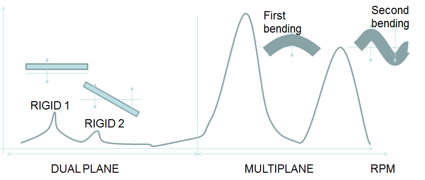
Critical speeds and modes
There is an important relationship between the number of critical speeds that one wants to balance and the number of planes required. One needs to have enough balancing planes for that. That is typically why one should need more than two planes to balance the first critical speed.
Difference between dual plane and multiplane
Planes and runs
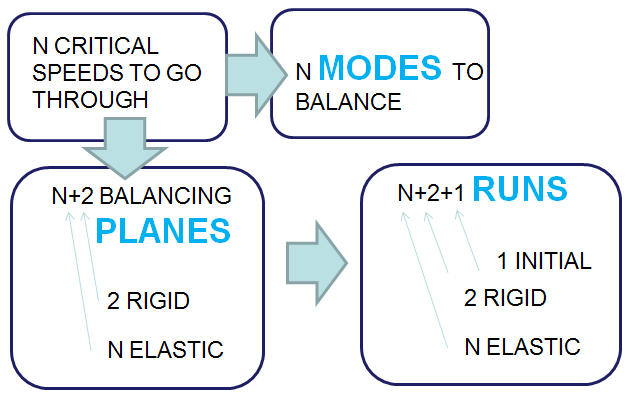
The number of runs required depends of the number of balancing planes on which one want to balance the rotor.
Relations between Planes and Runs
For each balancing, an initial run is required (without trial mass). Then there should be as many trials runs as there are planes (cf. picture above). Trial masses should be put at different positions in order to bring enough information.
The user can use steady state, run up, and shut down data. Nevertheless, the user should take care not to mix up the kind of data (for example: a run up for the initial test and shut down for the trial mass), as the mechanical behavior is different.
Measurement points and channels
A measurement point, connected to an instrument channel, is not necessarily linked to a correction plane. Vibration is measured at a bearing. There is not always the same number of channels as the number of planes. Nevertheless there should be enough channels to solve the problem. It is recommended to have at least one channel per balancing plane or relatively close to it.
A typical measurement configuration
Software main principles
- The software works in the office mode and is based on 1X data (amplitude and phase) versus RPM. The user will be able to select one or several speed ranges to be balanced.
- Data can be collected with OROS ORBIGate and exported as CSV files with the option" group by results". One can look at the CSV files example provided with the installation.
- The main steps are:
- Rotor configuration and trial masses positions
- Importing and selecting data (channels selection)
- Selecting the RPM range
- Processing the calculations
- Considering the correction weights and choosing the mounted masses
The configuration wizard
The main configuration wizard contains 5 main steps:
Configuration toolbar
The steps are detailed in the table below
| STEPS | Toolbar icon | Description |
| 1 |
| |
| 2 |
| |
| 3 |
| |
| 4 |
| |
| 5 |
|
By pressing "next" and "back" on each window the configuration steps can be accessed. Whenever it is required to access one of the windows independently, the icons toolbar can be used.
Getting started with the Multiplane balancing module
This chapter shows how to go through each step of the configuration easily and rapidly. In order to get more information on each step refer to chapter 3.
Starting the software module
Welcome screen: language choice
The software can be operated in 3 languages: English, German or French. Choose your language and press "START".
Project management
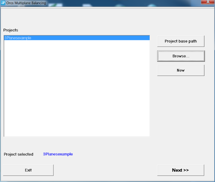
Use the example project provided with the software and open the project "3Planesexample". The project should have been placed into the balancing data directory as described in the installation guide.
Project window
Pressing "Next>>", the user will enter the configuration wizard and access the "Rotor configuration set-up".
Rotor configuration set-up
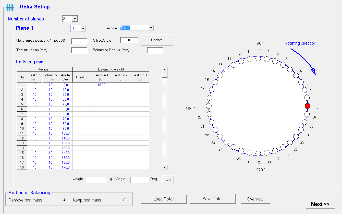
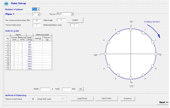
The next step is the configuration of the rotor. The rotor configuration is displayed for the 3planes example. This window let the user setup the number of planes. In the example, it is 3. The number of runs is automatically assigned as being the number of planes + 1 (the initial run): so 4 in the example.
The main point to be set up in these windows is the "Test run Masses" positions and weights for each run.
Rotor configuration set-up
Pressing "Next>>", the user will access the "1X Data import and selection".
Data import and selection
The purpose of that window is to import 1X data and select them. In the "3planesexample" project there are already some data.
The user can use steady state, run up, and shut down data. Nevertheless, the user should take care not to mix up the kind of data (for example: run up for the initial test and shut down for the trial mass), as the mechanical behavior is different.
1X data selection
Clicking the icon (
) will show the data.
Pressing "Next>>", the user will access the "Display configuration" window.
Runs display and RPM selection
This window is used to display the data and achieve the RPM selection.
The data can be displayed in several ways:
- For each channel (active or not)
- For each run
- In different display types (Magnitude, Phase, Polar, RPM)
Runs display and RPM selection
The RPM selection can be done by clicking the graph with the left button and dragging it to the right, click left and press enter with the keyboard.
Pressing "Next>>", the user will start the calculation and access the "Balancing weights" window.
Balancing weights
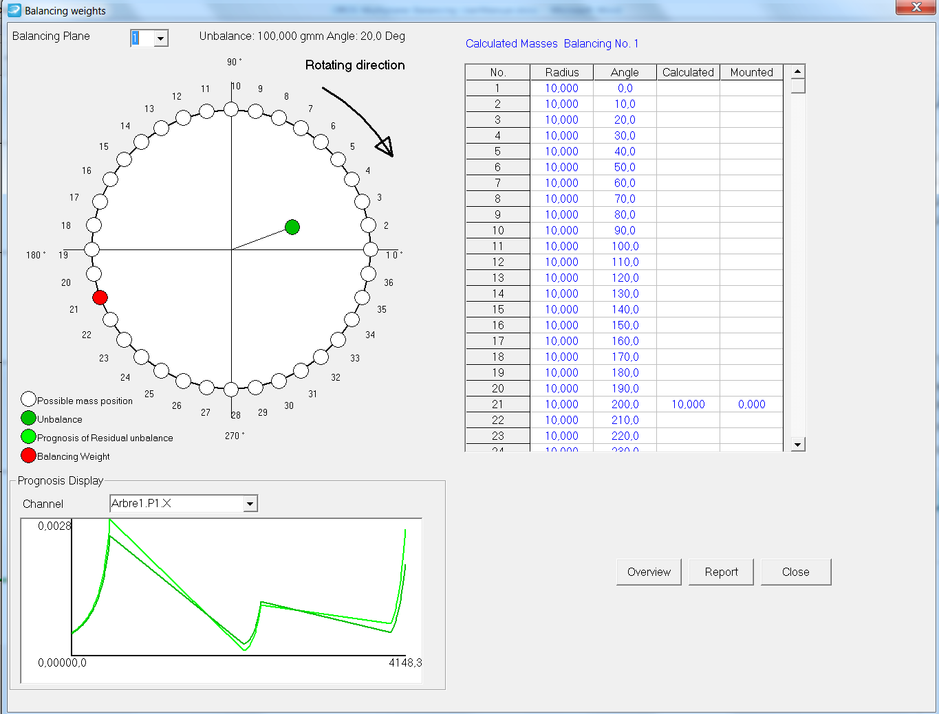
The balancing weights window is the where the correction weights recommendations are displayed.
Correction window
Getting further with the Multiplane balancing module
Project management
Projects allow the user to save and load a configuration.
Project: open an existing and create a new project
Projects are located in a project base. This project base can be selected with the button "project base path" (Read the installation guide about this).
Project base selection
Rotor set-up
Planes configuration
The number of planes should be selected first.
Positions are the places where one can put tests masses as well as correction masses on the rotor planes. One should enter the number of positions: they will be distributed evenly around the plane.
Then, one can configure each plane: test masses positions radius, and balancing radius for the positions.
Rotor set-up
There are two ways to enter the masses. One is to enter them in the table, the other is to enter them in the cells called "Weight" and "Angle". The angle should be an existing one. Otherwise a message will be issued saying that it is not possible.
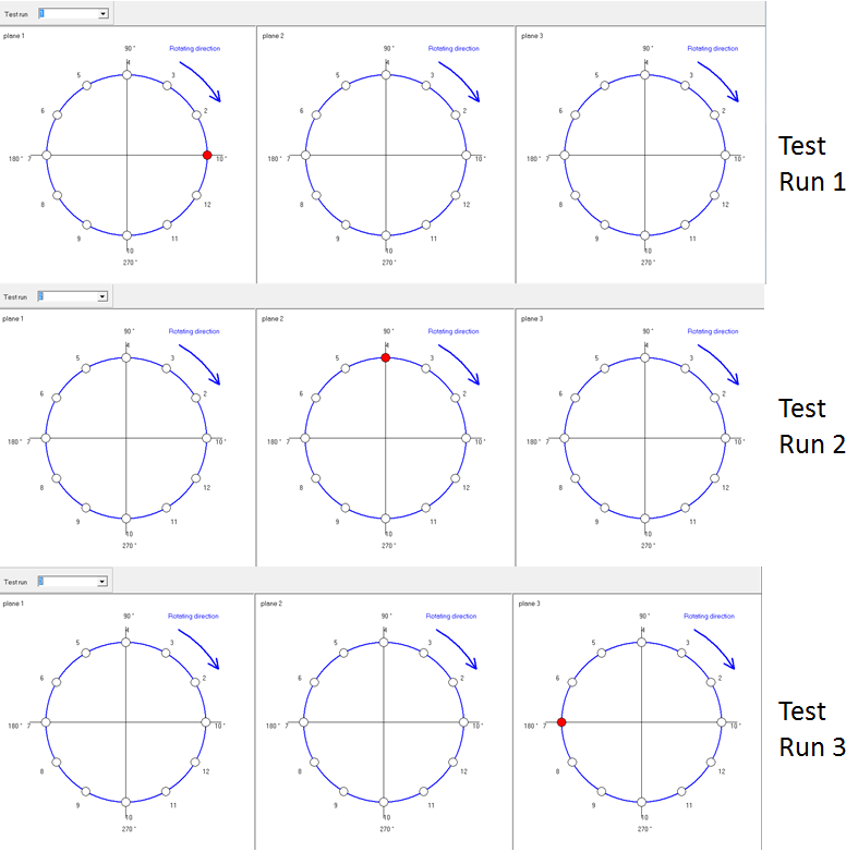
Overview
Clicking on the "Overview" button allows the user to display where the masses will be positioned on the balancing planes for each run.
Test runs overview
Method of balancing: Remove or Keep the test mass
There are two possibilities concerning the method to be used. The test mass can either be removed or remain. In most cases the test masse is removed, however, sometimes there is no possibility to do that such as situations where the test mass must be welded.
X data selection
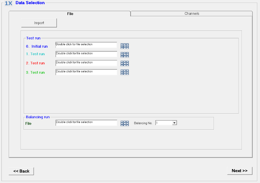
The base for balancing is 1X data (amplitude and phase). The data should be available in the ODR format. If the data is not available yet, it should be imported based on CSV files (with a format as defined by the example on the installation CD).
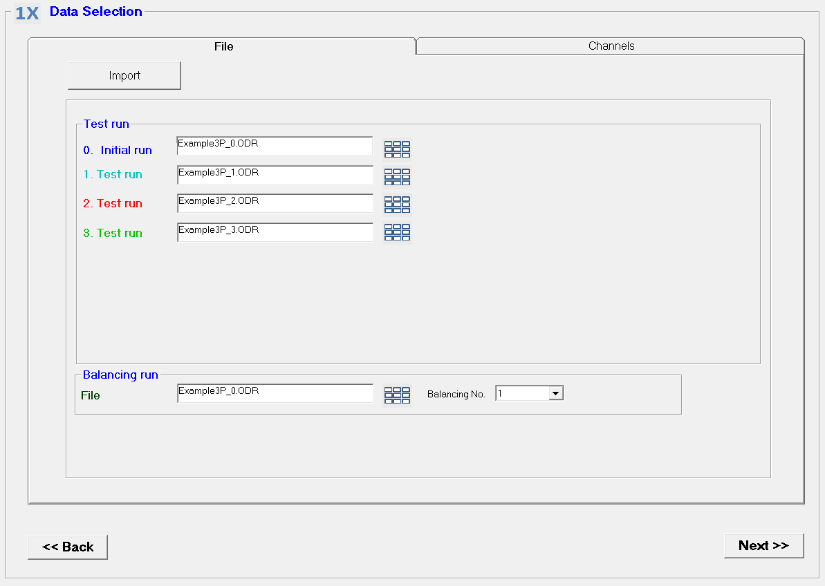
This window is where the data is selected. One should "double click" in the area aligned with the test run. It will open a window where the ODR file can be selected.
1X data selection
The balancing run is used when a balancing has already been achieved. At that stage one wants to balance further on the same machine. It is also called "trim balance".
Importing data
Exporting data from ORBIGate to CSV
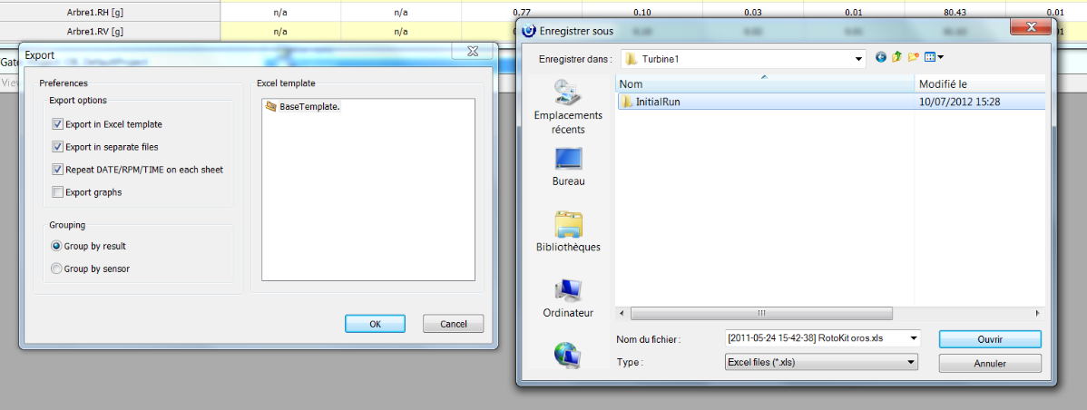
One should load a measurement file in the navigation mode of ORBIGate. Then proceed as follows:
Step 1: File/export.
Step 2: Select the appropriate choices in the export: "Export in Excel template", "Export in separate files", "Repeat Data, RPM, Time on each sheet" + "Group by result"
Step 3: Create a directory by the name of the run ("InitialRun" for example)
Step 4: Export the data.
Exporting CSV files from ORBIGate
Importing data from CSV to Balancing
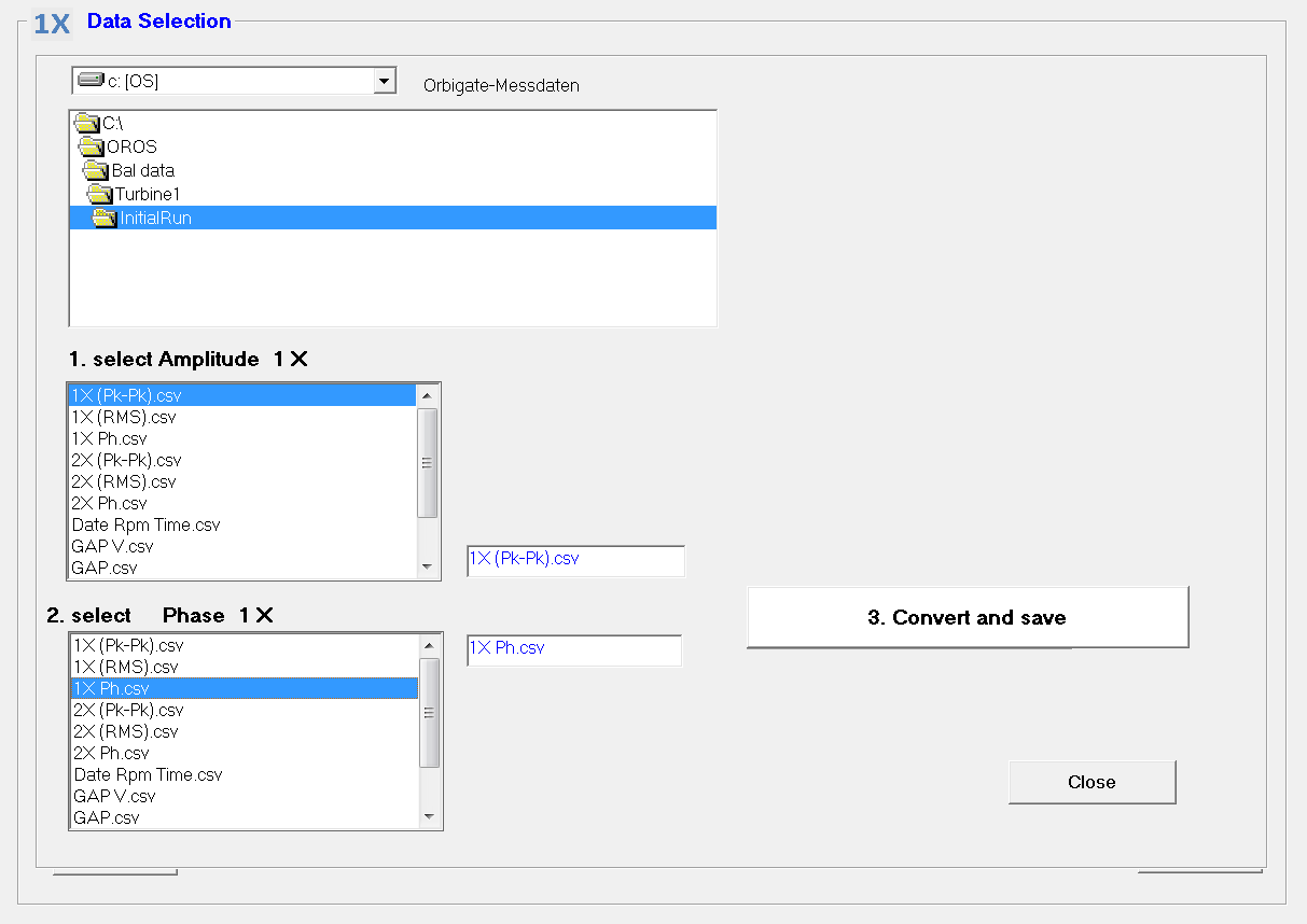
Importing data will convert CSV files to ODR files. The first step is to select CSV files from a directory. It should be displayed as in the window below. One can decide to select either (RMS) value or (Pk-Pk) values. Once the files are selected, press "convert and save". It will convert data to ODR files that are able to be used by the software.
Data importation window
Important notice:
- One should not import a file that contains both a run-up and a run-down.
- One should import data that contain data with the same physical dimension (acceleration, velocity or displacement).
Channels selection
Measurement files contain a number of channels. One doesn't need to use all the channels. It is possible to make them active (X) or not, by clicking in the cell. This is how they can be selected to be used or not for the calculations.
Channel selection window
In the display step (
), the channel will appear without a cross if it is the case, as shown in the figure below.
Appearance of channels activity in the display window step
Looking at the balancing data
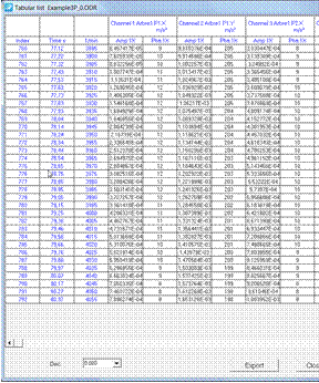
Clicking the icon (
) will show the data in a table looking as follows.
Data table
Runs display and RPM selection
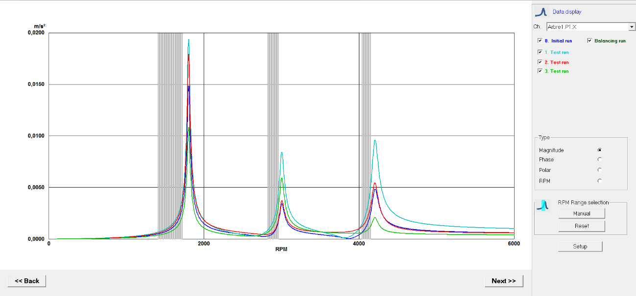
Runs display
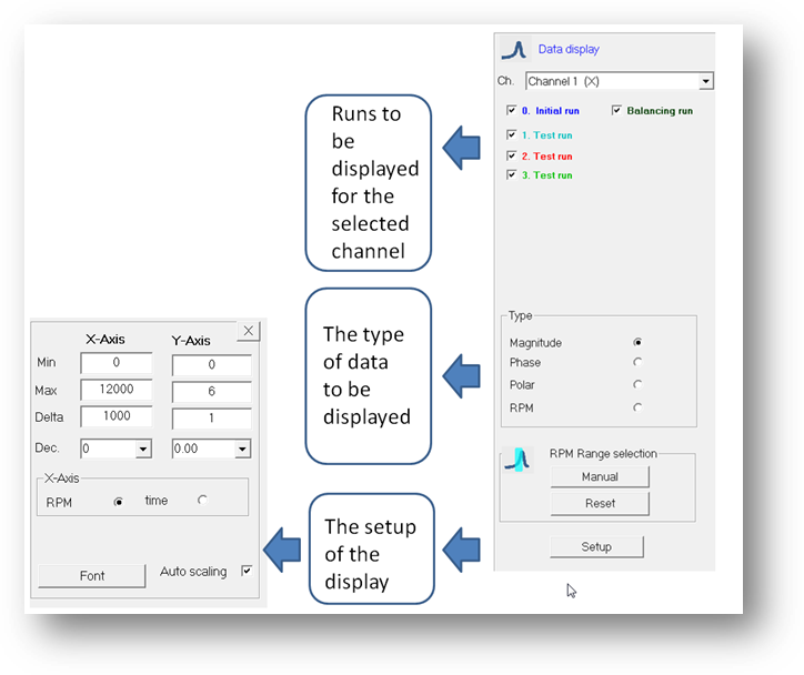
- As shown in the following window, one can select the data that should be displayed:
- For each channels (active or not)
- For each run
- In different display types (Magnitude, Phase, Polar, RPM)
Display options
By clicking in the setup button, one can access the display of the setup.
RPM selection
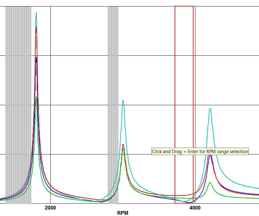
One of the major steps is to select the RPM range for the balancing. It is recommended not to select the critical speed itself as part of the RPM range. At this speed, the phase is changing a lot and it would not provide a good result. Typically, one should keep a 100 rpm distance from the peak during the RPM selection.
There are two ways to select the rpm range to be selected: graphical and manual.
- Graphical: The RPM selection can be done by clicking the graph with the left button and dragging it to the right, click left and press enter with the keyboard.
Graphical RPM range selection
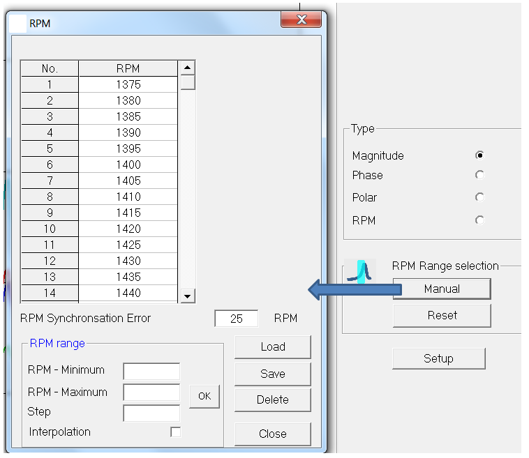
- Manual: The RPM range can also be selected manually with the "Manual" button as shown in the figure below.
The user can choose in the "RPM range" a number of settings:
- RPM-Minimum: is the lower end of the RPM range that should be considered
- RPM-Maximum: is the higher end of the RPM range that should be considered
- Step: is the RPM step that should be considered
Manual RPM range selection
The calculation
The calculation is triggered by pressing the calculation icon (
). When the calculation is finished the correction weights window will be automatically shown.
Correction weights window
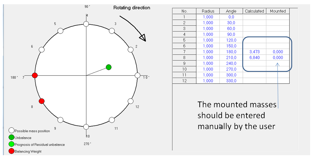
The software proposes the recommended correction masses in the correction weights window (
). They are shown on the graph and in the column "calculated".
Mounted masses
The user can choose to mount masses that are different than the calculated ones. The prognostics will show what the prognosed residual vibrations for each channel are.
Mounted masses window
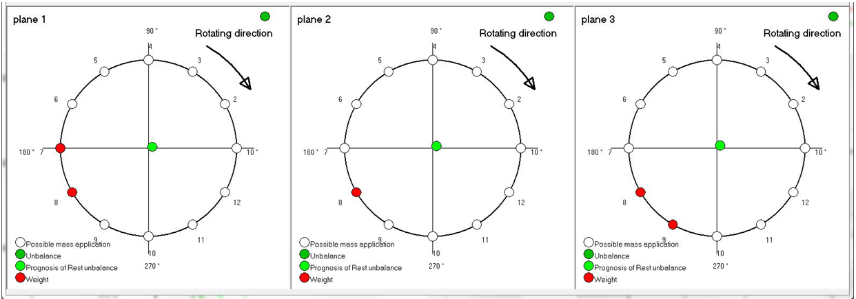
Overview
The overview button allows the user to access an overview picture of the correction recommendations for all planes.
Correction weights overview
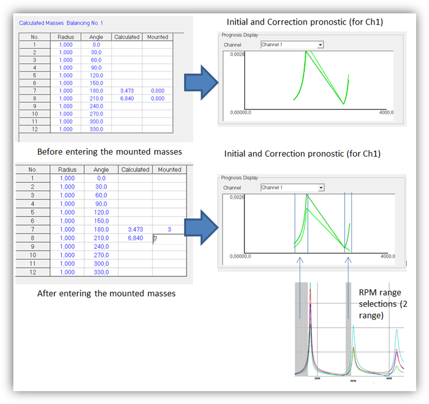
Prognostics
The prognostics is the vibration that can be expected at the selected channel. The prognostics are given as a function of the masses that are chosen to be mounted. The values should be entered in the cell "Mounted weights".
Prognostics window
Report
The report shows in a table, the history of the trial masses that were used and of the mounted masses. This is displayed for each plane. Each report can be exported to a TXT file.


