Difference between revisions of "XPod Bridge - Strain gauge"
| (9 intermediate revisions by the same user not shown) | |||
| Line 45: | Line 45: | ||
==Connection== | ==Connection== | ||
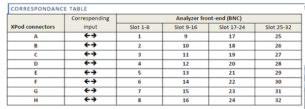
The Xpods feature 8 connectors on the side of the analyzer. The connectors correspond to the front-end channels located at the Xpod level by set of 8. | The Xpods feature 8 connectors on the side of the analyzer. The connectors correspond to the front-end channels located at the Xpod level by set of 8. | ||
[[File:correspondance_table.png| | [[File:correspondance_table.png|600px|none]] | ||
===Type=== | ===Type=== | ||
| Line 65: | Line 65: | ||
===Connectors Pinout=== | ===Connectors Pinout=== | ||
[[File:Annotation 2020-04-16 184550.png]] | [[File:Annotation 2020-04-16 184550.png|700px|none]] | ||
===Bridge connection === | ===Bridge connection === | ||
====Quarter bridge==== | ====Quarter bridge==== | ||
[[File:XPOD_gauge_wiki_quarter.png| | [[File:XPOD_gauge_wiki_quarter.png|700px|none]] | ||
====Half bridge==== | ====Half bridge==== | ||
[[Image:Strain_Gage_User_Guide_03.png| | [[Image:Strain_Gage_User_Guide_03.png|700px|none]] | ||
====Full bridge==== | ====Full bridge==== | ||
[[File:full.png]] | [[File:full.png|700px|none]] | ||
=== download === | === download === | ||
| Line 82: | Line 82: | ||
[https://orossas.sharepoint.com/:b:/g/support/EerOWioePhdAv8ioRwGCNAYBZe7TmmCnHF-oPxYOQz03Qw?e=KBG1I6 Download : OROS BRIDGE CONDITIONERS XPOD™ CONNECTIONS in .pdf] | [https://orossas.sharepoint.com/:b:/g/support/EerOWioePhdAv8ioRwGCNAYBZe7TmmCnHF-oPxYOQz03Qw?e=KBG1I6 Download : OROS BRIDGE CONDITIONERS XPOD™ CONNECTIONS in .pdf] | ||
== | ==Tutorial: how to set up XPOD conditioners for strain gage== | ||
===Hard Connection=== | ===Hard Connection=== | ||
| Line 91: | Line 91: | ||
[[Image:Strain_Gage_User_Guide_01.png|framed|none]] | [[Image:Strain_Gage_User_Guide_01.png|framed|none]] | ||
[[Image:Strain_Gage_User_Guide_02.png | [[Image:Strain_Gage_User_Guide_02.png|none]] | ||
Then solder the connector pins according to the pin-out diagram below: | Then solder the connector pins according to the pin-out diagram below: | ||
[[File:Annotation 2020-04-16 184550.png]] | [[File:Annotation 2020-04-16 184550.png|700px|none]] | ||
[[File:XPOD_gauge_wiki_quarter.png]] | [[File:XPOD_gauge_wiki_quarter.png|700px|none]] | ||
===Set up NVGate=== | ===Set up NVGate=== | ||
Revision as of 11:32, 13 March 2023
OROS analyzers feature optional XPod Wheatstone bridge conditioner.
Expander modules
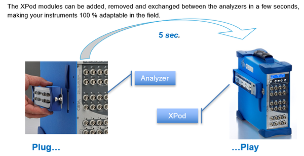
The XPod is a device that can be fixed on OR3X TW analyzer. Each XPod is associated to a block of 8 inputs.
In the connected mode, when and XPod is present each corresponding input can be routed to:
· The BNC input (Standard)
· The XPod connector
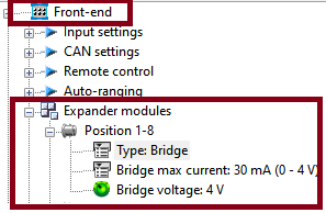
General Xpod settings
- Type: For acquisition setup preparation, the XPod presence can be simulated in the office mode:
One XPod type selector is available for each XPod position.
- Bridge max current: Select the max excitation current for the corresponding active Bridge Xpod. Each bridge Xpod excitation current can be limited to 30 mA up to 4 V and 12 mA up to 10 V.
- Bridge voltage: Select the excitation voltage for the corresponding active Bridge Xpod. From 0 to 10 V.
Input settings
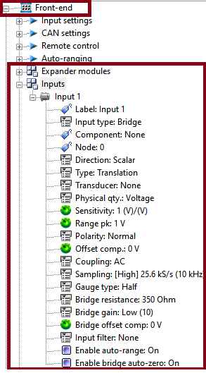
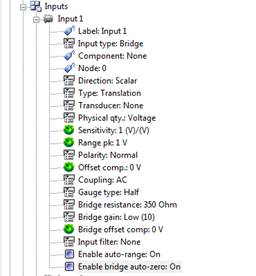
For each input, you can select the following options dedidctaed for Xpod gauge:
- Type: bridge signal conditioning for strain gauge.
- Gauge type: Full, Half or Quarter bridge mount. The completion resistors are included in the Xpod.
- Resistance: Bridge completion resistor: 120 or 350 Ohms for quarter bridge mount.
- Gain: Bridge gain: 10 or 100 depending on the required precision and range.
- Max current: the provided current can be limited to 30 mA up to 4 V and 12 mA up to 10 V.
- Excitation voltage: Each Xpod provides an excitation voltage from 0 to 10 V.
- Offset Comp.: Bridge offset comp: Can be used for manual balance of the bridge.
Connection
The Xpods feature 8 connectors on the side of the analyzer. The connectors correspond to the front-end channels located at the Xpod level by set of 8.
Type
The bridge conditioner XPod is delivered with its own connector + a connection kit with the following characteristics:
On the Xpod - Sub-D 9 pin - Female
Connector kit - Sub-D 9 pin - Male - Screwed connector bloc - Removable metal cover
Cables
We recommend using the following cable characteristics for wiring a strain gauge:
- Twisted pairs
- 6 wires
- Independent ground shields for each pair
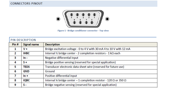
Connectors Pinout
Bridge connection
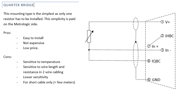
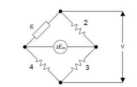
Quarter bridge
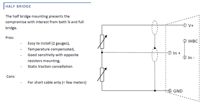
Half bridge
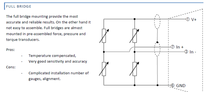
Full bridge
download
Download : OROS BRIDGE CONDITIONERS XPOD™ CONNECTIONS in .pdf
Tutorial: how to set up XPOD conditioners for strain gage
Hard Connection
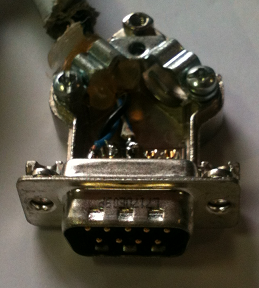
Let us see how to proceed a half bridge connection.
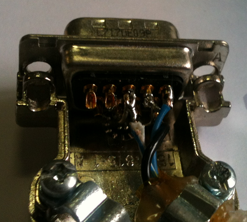
Use a male SUB D 9 pins connector and a "bullet proof" cable like Ethernet cable to link the strain gauges to the connector.
Then solder the connector pins according to the pin-out diagram below:
Set up NVGate
Sensitivity
In quarter bridge configuration, the gauge is usually glued toward the beam direction to measure the bending for example. In this case the right formula is
Where
- S = ΔEm/V is the sensitivity (*V / µdef)
- e , 2, 3 et 4 are the resistivity of the gauge or generated by the hardware depending on the type of the
bridge.Here, 2, 3 and 4 are XPOD internal resistors
- V, the excitation voltage (in NVGate, the settings is "Expender module/Bridge voltage")
- ΔEm, the strain measurement voltage
- r, equal to R1/R4=R2/R3 often equal to 1.
- Sg is the gauge factor (often equal to 2 x 1E-06 volts per micro-def
| - | n, the number of gauges (For full bridge, it’s 4. For ¼ bridge it’s 1.) |
You can notice that the sensitivity is not linear with the stress Δ = ΔL/L. For low strain, the formula is equivalent to:
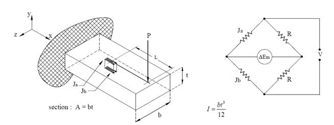
For a half-bridge configuration, it is possible to glue 2 gauges toward the beam direction as shown in the figure below:
In this case, the sensitivity is linear and is equal to:
So the fact that 2 gauges are used instead of only one gets the bridge sensitivity twice better.
NVGate setup
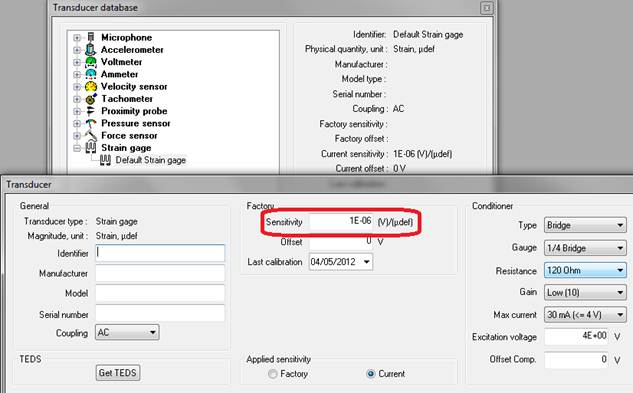
It is advised to first add a "transducer" in NVGate database in order to register the bridge configuration.
Browse the Home menu > Transducer tab > Database
Add a new transducer which is in fact a bridge configuration.
In the Conditioner area, fill the Gauge bridge type, the gauge resistance, the excitation voltage and so on.
The sensitivity to be filled is the bridge’s one (in red below). So, it is necessary to compute this sensitivity according to the above formula.
Measurement
The XPOD contains 8 inputs. In case of XPOD connection, the 8 BNC inputs are disabled for using the XPOD inputs.
These XPOD inputs can be connected to different plug-ins like FFT or Time domain analyzer for example.
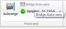
Then the bridge has to be balanced through the Bridge Auto-zero feature (this option has to be setup to ON in the Input settings).
Press on « Bridge Auto-zero » from the "measurement" tab to start the bridge balancing. This step may last about 30 seconds.
Now, the measurement is ready to start.

