Modbus TCP/IP to NVGate
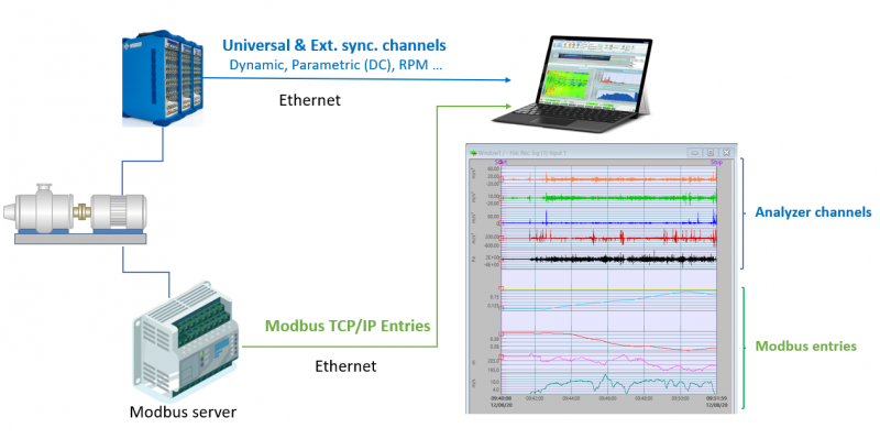
This add-on allows NVGate to read inputs with Modbus TCP/IP protocol. It converts bus values to Simulated DC input and can be used as physical inputs in NVGate, which are synchronized with dynamic / parametric / Ext. sync. channels acquired from OR3X or O4 analyzer. It supports all the Modbus register types. This add-on can also update or create properties that are metadata stored in the NVGate measurements. The metadata can be computed from one bus value (min, max, average, first, last) or can be read from a file.

Download
Requirements
- NVGate version 15 (2022) or greater.
- Modbus to NVGate add-on.
- Your own TCP/IP Modbus server or the demo server provided with Modbus to NVGate.
Procedure
Please follow the following steps:
1. Copy the Modbus folder on your PC.
2. Launch NVGate.
3. Launch the Modbus server (you can first use the test server launching test_server.exe from the Modbus folder).
4. Launch ModbusToNVGate.exe.
5. Select the inputs file (sample_standard_f1.xlsx in the Modbus folder).
6. Select the properties file (sample_properties.json in the Modbus folder).
7. Click on start.

8. In NVGate, in the analyzer Setting Browser / Front end / Simulated DC Inputs, you’ll see that Simulated DC Values are collected.

From Acquisition / Connect Inputs, you can drag and drop the DC simulated channels (in the DC inputs tab) in a module (Recorder for example):

Recording
The add-on detects Recording starts and stops in NVGate. When properties are defined in the Input file, they are updated when the recording stops.
Input file
This file contains the list of data to be read from the server:
- General
- Label: Name of the input displayed in NVGate.
- User unit: the unit as described in the Units.xlsx
- Min value and Max value: The minimum and maximum value (expressed in user unit). The min value must correspond to Bus data min, and the max value must correspond to Bus data max, i.e., if a temperature in [-20, 100] can be encoded on the bus with values in [-200, 1000]. So, range min = -20 and max = 100.
- Modbus input
- Address: the register address.
- Type: type of MODBUS request (among Discrete Input, Internal Bits, Holding Register, Input Register).
- Bit: for Discrete Input or Internal Bits, the position of the bit in the register
- Bus min, Bus max: Bus data: see range (in this example, the values must be min = -200 and max = 1000).
- NVGate Simulated DC number: Must be in [1, 32].
- Measurement properties (the parameters are metadata written in the measurement when the recording stops. They are accessible from Measurement Properties in NVGate.)
- Name: the name displayed in NVGate.
- Method: how the value is computed (first, last, min, max, average). If the method is ‘file’, the value is read from the Properties file.
- # digits after dot: value rounding.

Properties file
A JSON file giving the value of some properties. The method of the property must be ‘file’.
Unit file
The conversion coefficient between the units from MODBUS and the NVGate default unit (in International System of Units, SI).
ModbusToNVGate.ini
The ModbusToNVGate.ini file contains:
- Server IP and port.
- NVGate server IP and port (when NVGate is executed on a different PC from the Modbus to NVGate add-on)
- Modbus RTU mode (advanced usage): enable RTU mode with 1.