Modal ODS and Modal(EMA-OMA) identification
ODS & Modal Analysis
Modal can deal with Operating Deflection Shape (ODS) Analysis and two types of modal analysis: Experimental Modal Analysis (EMA, both input and output data are available) and Operational Modal Analysis (OMA, only output data are available).
You can find out how a machine or structure moves during its operation via ODS, which shows the overall dynamic characters of the structure or machine.
You can get the modal parameters of structures via EMA or OMA, by performing the following four steps: (1)Signal processing to get frequency response functions (for EMA) or output power spectrum matrices (for OMA); (2) Selecting an appropriate identification algorithm;(3)Doing modal identification; (4) Operating the identification results, such as viewing mode shapes, copying, and removing, and so on.
Almost all the algorithms begin with the Modal Indicator Function (MIF).
The following modules are available in Modal: TD ODS, FD ODS, EMA Narband (CMIF), EMA SelBand-SIMO (RFOP), EMA SelBand-MIMO 1 (FDPR), EMA SelBand MIMO 2 (RFPM), EMA BroBand (BBFD), OMA NarBand Full (FSDD), OMA NarBand Half (CMIF), and OMA BroBand (OBFD). A NarBand method means an algorithm performed in a narrow frequency band, who has the biggest advantage of simple and easy to use. You can identify the modes only by picking the peaks of MIF one by one. A SelBand method means an algorithm performed in one or several selected frequency bands. A BroBand method means an algorithm performed in a broad frequency band or even the full frequency band sometimes.
An effective tool Modal Assurance Criterion (MAC) is also provided to validate the result of modal identification.
Modal Analaysis process illustration
Selecting an Algorithm
Before modal identification, you should select an appropriate algorithm according to the analysis type (EMA or OMA) and number of input (SIMO or MIMO). You can select the specified algorithm by mouse click on the corresponding item in the "Workspace" shortcut pane. A message will appear if you success in doing this.
Another appropriate algorithm can be selected for necessary. And you can compare the results from different algorithms. If some selected algorithm is not fit for the current case, you will be prompted to select another one.
Doing Modal Identification
It’s recommended to employ the modal indicator function (MIF) for the modal identification in the frequency domain. The identification process varies according to different type of algorithms.
- Narrow-Band Identification Algorithm
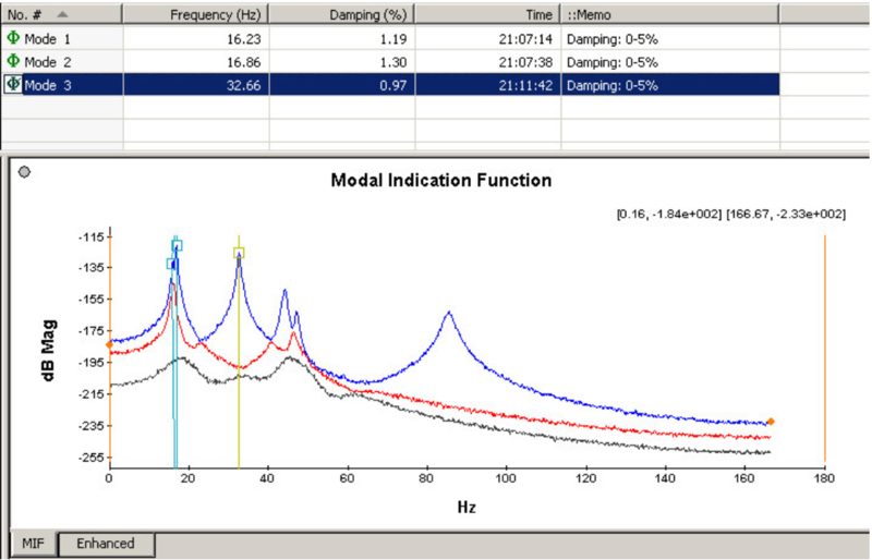
(1) Open the MIF curves interface by pressing the ![]() button in the toolbar, and the following interface will appear:
button in the toolbar, and the following interface will appear:
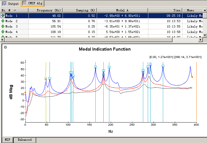
The interface consists of two mode list views and a tab window view (’MIF’ tab and ’Enhanced’ tab ). The two mode list view is synchronous. You can adjust the separator lines to resize these views.
(2) Press the![]() button in the toolbar to begin the NarBand modal identification.
button in the toolbar to begin the NarBand modal identification.
(3) Check the identified results and curve fitting of enhanced curves. All the identified modes will be shown in the two mode list views and output shortcut pane. You can check the relevant enhanced curves and its curve fitting in each setup for each mode. If ideal curve fitting hasn’t been got, you can adjust the fitting band manually, and identify this mode again in the current setup by double clicks.
- Select-Band Identification Algorithm
(1) Open the MIF curves interface by pressing the ![]() button in the toolbar.
button in the toolbar.
(2) Select the identification frequency band. Move the cursors by mouse or keyboard to the frequency point you want, then double click the mouse or press Enter key to select this band. As a result, a tag like "[-]" appears to indicate this selected band. The data in this band will be used for modal identification. Multiple selected bands for the identification are allowed in Modal, and all the data in these bands will be used to identify modal parameters. To delete the latest selected band, you can use the ![]() button in the toolbar, or by the mouse’s middle click. To delete all the selected bands, you can use the
button in the toolbar, or by the mouse’s middle click. To delete all the selected bands, you can use the ![]() button in the toolbar, or by the mouse’s middle double clicks.
button in the toolbar, or by the mouse’s middle double clicks.
(3) Specify the modal order in the selected bands. MIF plot can be used to indicate the modes existence efficiently. A peak in this plot means a mode. For example, in the selected band of the following figure, four modes are detected, including two heavily closed modes.
(4) Press the ![]() button in the toolbar to begin modal identification with selected algorithm.
button in the toolbar to begin modal identification with selected algorithm.
(5) Check the results. The synthesized FRF/HPSD curves will appear in the main window after identification, and the result will be shown in the output shortcut pane. At the same time, an item corresponding to the selected identification algorithm will appear under the directory of ’Data\Setup1\Mode’ in the workspace shortcut pane.
Double click on this item will show the identified mode list.
3. Broad-Band Identification Algorithm
The process of Broad-Band algorithms is almost the same with Select-Band algorithms, only that broader or even full frequency band can be set for the Broad-Band identification.
Operating the Results
Detailed information on identified modal frequencies, damping ratios, identification time, if structural mode are displayed in the mode list view. You can sort the modes ascending or descending according to the specified keyword by clicking on this column header. Also you can do many other operations by the toolbar or right click popup menu, such as deleting modes, copying modes, viewing the mode shapes, exporting the modes, and so on.
You can also double click on the icon of ’’ in the front of each row to view the mode shape animations. The mode shape animations are an import criterion of modal identification.
Modal Indicator Function (MIF)
A very important step of modal identification is to determine how many modes are contained in a selected frequency band. MIF plot is a very good tool to achieve this, indicating the modes efficiently.
MIF can be employed in not only EMA, but also OMA. The number of MIFs equals the number of excitations or references. The MIFs consist of the singular values of frequency response function matrix (FRF), output power spectral density matrix (OPSD), or half power spectral density matrix (HPSD).
By the powerful singular value decomposition, the real signal space is separated from the noise space. Therefore, the MIFs exhibit the modes effectively. A peak in the MIFs plot usually indicate the existence of a structural mode, and two peaks at a same frequency point means the existence of two repeated modes. Moreover, the magnitude of the MIFs always implies the strength of a mode.
Sometimes we should note the cross modes, for example
As showed in the above figure, the peak in the second MIF curve doesn’t indicate a mode. It’s formed by the cross of two modes.
Operating Deflection Shape
Time domain ODS
With Modal, you can animate time domain ODS directly from multi-channel data that was acquired spatially from a machine or structure. This is done by sweeping a cursor through a set of time histories. You can stop the animation, back it up, and play it forward to observe in slow motion vibration phenomena that may have taken place very quickly.
Frequency Domain ODS
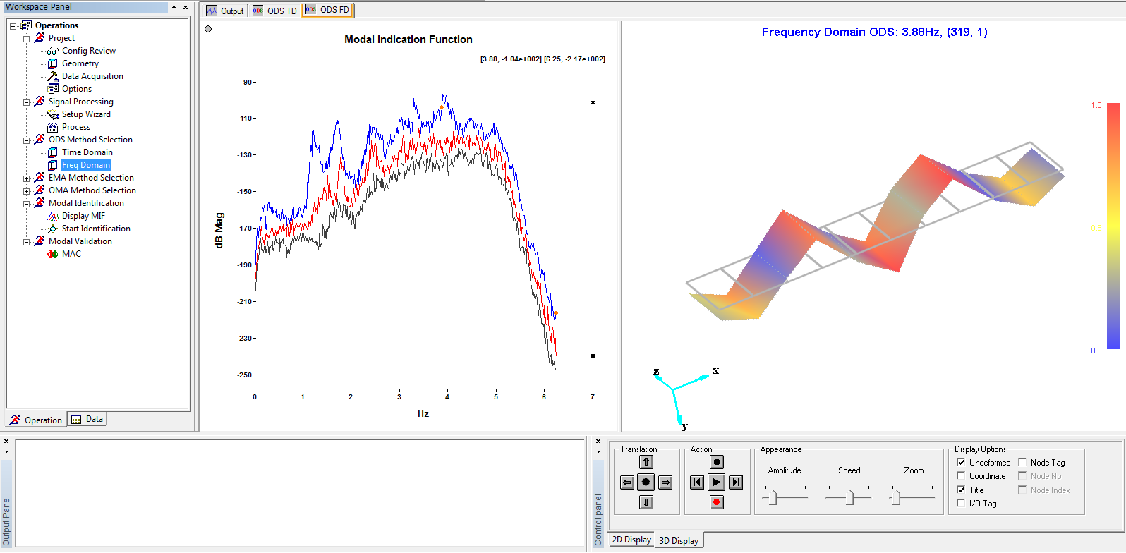
With Modal, you can animate frequency domain ODS directly from data that was acquired spatially from a machine or structure. This is done by sweeping a cursor through a set of frequency domain measurements, or dwelling at a specific frequency. A FD ODS allows you to see how a structure behaves at a single frequency.
Modal Analysis
Modal identification methods
Modal analysis can be conducted via artificial excitation, e.g. shaker or instrument hammer excitation, and input force and output responses are measured. That is normally called an Experimental Modal Analysis (EMA). Modal analysis can be also accomplished during operational conditions of a mechanical structure via responses measurements due to ambient or natural excitation, or other excitation but without input force measurements. This is called as Operational Modal Analysis (OMA).
Modal identification algorithms can generally be divided into 2 categories: Time domain (TD) techniques and frequency domain (FD) techniques. TD modal identification has the advantage of estimation of all the modes in the frequency band of interests at once. However, all the TD modal identification algorithms have common unfavorable feature, difficulty to distinguish physical (structural) modes from computational (noise) modes. For application to real-world structure, to locate structural modes reliably is the most important task of a modal analysis. This is why only FD techniques are implemented in OM2.
| EMA | OMA |
EMA approach can be divided into three levels based on Single Input Single Output (SISO), Single Input Multiple Outputs (SIMO), Multiple Input Multiple Outputs (MIMO). Modal is born in MIMO. However, SIMO algorithm is also implemented for preliminary application. MIMO EMA has important advantages: not only consistent results can be obtained, but close spaced and even repeated modes can be identified. A modal Indication function (MIF) is calculated via Singular-Value-Decomposition (SVD) of the frequency Response Functions. |
OMA is a powerful tool to extract dynamic characteristics of real world structure from output-only measurements during operational conditions. The output response can be generated by ambient or natural excitation as well as artificial broadband excitation (but without input force measurements). A modal Indication function (MIF) is calculated via Singular-Value-Decomposition of Power Spectrum Density (PSD) matrix or Half Power Spectrum Density (HPSD) matrix. |
| OMA Narband Full | |
Narrow-band operational modal identification algorithm in frequency domain.
| |
| EMA Narband | OMA Narband Half |
Narrow-band MIMO modal identification algorithm.
|
Narrow-band MIMO modal identification algorithm.
|
| EMA Selband SIMO | |
Selected-band SIMO modal identification technique, suitable for the modal test with only one excitation or one reference, e.g., a single shaker or single reference for impact tests.
|
|
| EMA Selband MIMO1 | |
Selected-band MIMO modal identification technique.
|
|
| EMA Selband MIMO2 | |
Selected-band MIMO modal identification technique.
|
|
| EMA Broadband | OMA Broadband |
Broad-band MIMO modal identification technique.
|
Broad-band operational modal identification technique.
|
Narband (CMIF)
Complex Mode Indicator Function (CMIF), is an narrow band modal identification algorithm in the frequency domain. CMIF an easy-to-use method. You should use it as the following steps:
Selecting a Peak
Press the button ![]() in the toolbar, and click the MIF plot to activate it. A red cross marker ’十’ will appear, who is able to find the local peak automatically. The index and coordinate value of the marker are shown in the top left corner of MIF graph. In the figure below, (99,1):[47.85,3.48e+001] means that the cross cursor is now at the 99th point of the first MIF curve, and the coordinate is (47.85, 34.8).
in the toolbar, and click the MIF plot to activate it. A red cross marker ’十’ will appear, who is able to find the local peak automatically. The index and coordinate value of the marker are shown in the top left corner of MIF graph. In the figure below, (99,1):[47.85,3.48e+001] means that the cross cursor is now at the 99th point of the first MIF curve, and the coordinate is (47.85, 34.8).
Auto Identification
After selecting the peak, you should double click to finish this identification. The identified results will be shown in the MIF plot, mode list and output shortcut pane. Each identified mode will be marker with a shape symbol. Its middle pane indicates the position of peak, and the line points to the identified frequency. The mode selected in the mode list will be marked yellow in the MIF plot while the others are blue.
Checking curve fitting and Refitting
You can check the quality of curve fitting by selecting some mode in the mode list and then turning to the ’Enhanced’ tab page. Seen from below, the blue one is the enhanced FRF curve, and the red one is its fitting curve. Sometimes the identification result is not good because of the automatically selected band is not the best. Thus you can move the two cursors to select a better band, then double click to identify this mode again.
Selband SIMO (RFOP)
Rational Fraction Orthogonal Polynomials (RFOP), is an SIMO modal identification algorithm in the frequency domain. It is suitable for cases with only one excitation or one reference. RFOP can fit the FRFs or HPSDs in a fairy broad frequency band.
Each parameter is defined as the following:
Input Number
Number of excitations or references. It is automatically displayed by the software, and can only be 1 in the RFOP algorithm.
Output Number
Number of excitations or non-references. It is automatically displayed by the software.
Denominator Order
Rational fraction math model is used in the RFOP algorithm, and the order of denominator is twice of the modal order in the selected frequency band. Generally you can confirm the modal order by the MIF plot. In some cases, the modal order should be increased properly to hold the noisy modes, and the noise modes can be deleted by the criterion on damping ratios and mode shapes.
Modal Order
This parameter varies with the denominator order you set. You should ensure that this value equal or larger than the real modal order in the selected frequency band.
Numerator Order
This parameter varies with the denominator order you set, and keeping equal to it. You are allowed to set this value individually to be larger than the denominator order, for the sake of compensating for the out-band modes.
Selband MIMO1
Frequency Domain Poly-reference (FDPR), is a MIMO modal identification algorithm in the frequency domain. It is suitable for cases with multiple excitations or multiple references. FDPR usually fits the FRFs or HPSDs in a narrow frequency band. The outstanding advantage of FDPR is its highly easy-to-use.
Besides the MIF plot, two another bar graphs are provided for you to confirm the modal order in the selected frequency band according to the bars’ height. The upper graph shows the relative height of each mode, and it indicates the first four modes are greater than others. The lower graph shows the ratio of previous mode vs. next mode. You will find the fourth one is extremely high. It means that there are 4 structural modes, and the rest are ’noisy modes". So, here you should specify the system order to 4.
Each parameter is defined as the following:
Number of Bars
Number of bars shown in the graph, default as 10. The minimum value of this parameter is 2, and the maximum value is the output number of FRFs. You can change this value to view the bas more clearly.
Order of System
Modal order in the selected frequency band. Generally a fairy good value will be automatically set according to the practice. You are also allowed to change this value to get better result.
EMA Selband MIMO2
Rational Fraction Orthogonal Polynomials for MIMO (RFPM), is a MIMO modal identification algorithm in the frequency domain. It is suitable for cases with multiple excitations or multiple references. RFPM can fit the FRFs or HPSDs in a fairy broad frequency band.
Each parameter is defined as the following:
Input Number
Number of excitations or references. It is automatically displayed by the software.
Output Number
Number of excitations or non-references. It is automatically displayed by the software.
Denominator Order
Matrix form fractional fraction math model is used in the RFPM algorithm, and the order of denominator is related with the modal order in the selected frequency band. Generally you can confirm the modal order by the MIF plot. The product of denominator order and input number should be larger than twice of the modal order. When the product of denominator order and input number is larger than the twice of the modal order, noisy modes will be identified, which can be deleted by the criterion on damping ratios and mode shapes.
Modal Order
This parameter varies with the denominator order you set. You should ensure that this value equal or larger than the real modal order in the selected frequency band.
Numerator Order
This parameter varies with the denominator order you set, and keeping equal to it. You are allowed to set this value individually to be larger than the denominator order, for the sake of compensating for the out-band modes.
EMA Broadband (BBFD)
The BroBand modal identification module is based on the algorithm of Polyreference Least Squares Complex Frequency (p-LSCF), developed in 2003. p-LSCF is a frequency MIMO modal identification algorithm which has superior performance compared to most time domain MIMO techniques, such as Polyreference Least Squares Complex Exponential (PRCE or LSCE), Extended Ibrahim Time Domain (EITD), and Eigensystem Realization Algorithm(ERA). BroBand EMA makes use of measured Frequency Response Function (FRF) as source data.
Features/Advantages of EMA Broband
EMA BroBand does not suffer from numerical problems, i.e. ill-conditioning problem in computing poles of the system in broadband as most frequency domain modal identification algorithm, e.g. Rational Fraction Orthogonal Polynomial (RFOP) and Frequency Domain Polyreference (FDPR), encountered. Compared to SelBand techniques, BroBand can then be applied to identify all the modes in a wide, including full, frequency band of interest at one time.
Compared to most time domain modal identification techniques, such as well know Polyreference (or Least Squares) Complex Exponential (PRCE, or LSCE) technique, :BroBand yields extremely clear stability diagram, making it much easier to select structural modes, or the physical poles, from which modal frequencies and damping ratios can be readily obtained.
The BroBand modular in OM2 has the feature of automatic modal sorting capability, i.e. BroBand can automatically distinguish structural modes from "noise" modes, or real modes from spurious modes.
Main Procedures for EMA BroBand
Major procedures for modal identification with EMA Broband are as follows:
- Select a frequency band
The EMA Broband can be used to identify all modes in a broad frequency band, including full band. However, frequency band selection may be advantageous and is suggested in the cases as:
- In the "soft" suspension of test article to simulate free-free boundary condition, so called "rigid-body modes" are sometime weakly excited in low frequency range. In this case, frequency band selection excluding this low frequency range is suggested for identification of flexible structural modes. The "rigid-body modes" can also be obtained with selection of corresponding low frequency band.
- A structure under testing sometimes shows "strong mode" or "global modes" in specific frequency band, and "weak modes", or "local modes" in other frequency band. These "strong/global modes" and "weak/local modes" can be easily observed from Modal Indication Function (MIF) plot based on height of the MIF peaks. In this case, it is suggested to divide the full band into few sub-band which cover "strong/global modes" and "weak/local modes", respectively.
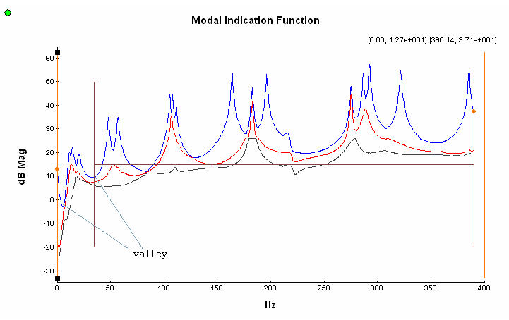
- It is suggested to start the frequency band from a valley of the MIF plots, and end the band at a valley too. According to our experience, such a frequency band can yield better result.
- Start Identification
Press the button of "Start Identification" ![]() in the toolbar to start modal identification.
in the toolbar to start modal identification.
- Modal Order determination
Preliminary determination of the number of modes in the selected frequency band according to the MIF plot, and fill it in the edit box of "Preset Modes No." Then the BroBand software will calculate a default "minimum order" according to this number. The relationship between "Preset Modes No." and "Minimum Order" is: minimum order = (preset modes No)*Ni/2, where Ni means the number of input.
Change the number of "Order Span" if necessary. The BroBand software will estimate the poles with a range of system order from "Minimum Order" to "Maximum Order", where Maximum order= Minimum order + Order Span-1. The default order span is 12.
"Start Modal ID"
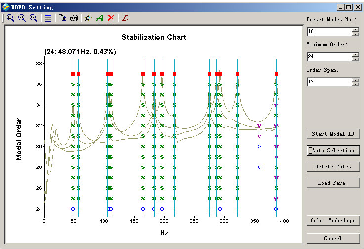
Press the button of "Start Modal ID" or ![]() to obtain frequency stability diagram. This operation might take a little longer time to finish a complex structure with large number of modes and measurement coordinates. In the stability diagram, a shape symbol represents one pole. A pole in this diagram may represent a physical (i.e. structural) mode or a spurious (or noise) mode. It is normally not difficult to distinguish physical/structural) mode from spurious/noise mode by the distribution of poles. Generally speaking, a physical/structural mode can be identified in each proper number of orders, while for a spurious/noise pole it usually is not the case. There are five kinds of symbols to indicate the poles:
to obtain frequency stability diagram. This operation might take a little longer time to finish a complex structure with large number of modes and measurement coordinates. In the stability diagram, a shape symbol represents one pole. A pole in this diagram may represent a physical (i.e. structural) mode or a spurious (or noise) mode. It is normally not difficult to distinguish physical/structural) mode from spurious/noise mode by the distribution of poles. Generally speaking, a physical/structural mode can be identified in each proper number of orders, while for a spurious/noise pole it usually is not the case. There are five kinds of symbols to indicate the poles:
| Symbol | Description |
| o | The pole is not stable. (The poles obtained from the first order are always considered as unstable.) |
| f | The frequency of the pole does not change within the tolerance of 1%. |
| v | The frequency of the pole does not change within the tolerance of 1%, and the pole vector does not change within the tolerance of 10%. |
| d | The frequency of the pole does not change within the tolerance of 1%, and the damping of the pole does not change within the tolerance of 10%. |
| s | Both frequency, damping and vector are stable within the tolerances: the frequency of the pole does not change within the tolerance of 1%; the pole vector does not change within the tolerance of 10%; and the damping of the pole does not change within the tolerance of 10%. |
- "Auto Selection" of structural modes
Press the button of "Auto Selection" or ![]() , the OM2 selects the physical/structural modes automatically. While move the mouse cursor on a pole, the modal frequency and damping ratio corresponding to this pole will be shown. You can move the mouse on different poles to check the stability via small change of the modal frequency and/or damping ratio.
, the OM2 selects the physical/structural modes automatically. While move the mouse cursor on a pole, the modal frequency and damping ratio corresponding to this pole will be shown. You can move the mouse on different poles to check the stability via small change of the modal frequency and/or damping ratio.
You can zoom in to check part of the stabilization diagram by click and drag a rectangle with the mouse.
- Manually selection of physical/structural poles
A pole can also be manually selected by clicking it or deselected it by same operation. A selected pole will be marked with a shape symbol ![]() .
.
- Mode shape calculation
Press the button of "Calc. Modeshape" to confirm the pole section and BroBand software start to estimate the mode shapes and to calculate the synthesized FRFs.
- Inspection of identified modal parameters
Open the view of mode list. Yyou can check the identified result here: modal frequencies, damping ratios, modal A, modal B, and mode shape animations.
- Continue modal identification in another frequency band
If more than one frequency band is selected, returning to the MIF plot window, and repeat the above operations. The result obtained from previous modal identification can also be loaded by pressing the button of "Load Para.".
On the Toolbar of "BBFD Setting" Diagram
|
|
Display the full band of current curve |
| Back to previous display range | |
| Go to next display range | |
| Show or hide the graph grid | |
| Copy contents in current main window to the clipboard | |
| Save current snapshot to BMP or JPG | |
| Start modal identification to gain poles | |
| Select the structural poles automatically | |
| Delete all the selected poles | |
| Load the parameters (poles, selected poles, frequency band) of previous modal identification |
OMA NarBand Full (FSDD)
Frequency Spatial Domain Decomposition (FSDD), is an OMA modal identification algorithm in the frequency domain. FSDD an easy-to-use method. You should use it as the following steps.
Selecting a Peak
Press the ![]() button in the toolbar, and click the MIF plot to activate it. A red cross marker will appear, who is able to find the local peak automatically. The index and coordinate value of the marker are shown in the top left corner of MIF graph. In the figure below, (201,1):[32.71,-1.25e+002] means that the cross cursor is now at the 201st point of the first MIF curve, and the coordinate is (32.71Hz, -125dB).
button in the toolbar, and click the MIF plot to activate it. A red cross marker will appear, who is able to find the local peak automatically. The index and coordinate value of the marker are shown in the top left corner of MIF graph. In the figure below, (201,1):[32.71,-1.25e+002] means that the cross cursor is now at the 201st point of the first MIF curve, and the coordinate is (32.71Hz, -125dB).
Auto Identification
After selecting the peak, you should double click to finish this identification. The identified results will be shown in the MIF plot, mode list and output shortcut pane. Each identified mode will be marker with a ![]() shape symbol. Its middle pane indicates the position of peak, and the line points to the identified frequency. The mode selected in the mode list will be marked yellow in the MIF plot while the others are blue.
shape symbol. Its middle pane indicates the position of peak, and the line points to the identified frequency. The mode selected in the mode list will be marked yellow in the MIF plot while the others are blue.
Checking curve fitting and refitting
You can check the quality of curve fitting by selecting some mode in the mode list and then turning to the 'Enhanced' tab page. Seen from below, the blue is the enhanced PSD curve, and the red is its fitting curve. Sometimes the identification result is not good because of the automatically selected band is not the best. Thus you can move the two cursors to select a better band, then double click to identify this mode again. It should be noted that you should check the fitting curve for each setup, and refit for each setup if necessary. You can switch between each setup by the 'Setup No.' list box in the standard toolbar.
OMA BroBand (OBFD)
The BroBand Modal Identification Modula is bases on the algorithm of Polyreference Least Squares Complex Frequency (p-LSCF), developed in 2003. p-LSCF is a frequency MIMO modal identification algorithm which has superior performance compared to most time domain MIMO techniques, such as Polyreference Least Squares Complex Exponential (PRCE or LSCE), Extended Ibrahim Time Domain (EITD), and Eigensystem Realization Algorithm(ERA). EMA BroBand makes use of measured Frequency Response Function (FRF) as source data. OMA BroBand, which shares the same modal identification algorithm, on the other hand uses measured Half Power Spectrum Density (HPSD) as source data. As a result, a signal processing procedure to estimate the HPSD is required before the modal identification.
Estimate the HPSD
You should begin the HPSD estimation by using the "Signal Processing Wizard". The main procedures are as the following.
1) Select to estimate the Output Half PSD:
2) Remove the trend of signal:
3) Perform decimation if necessary:
4)Set the FFT parameters:
5) Apply the exponential window function:
Here the exponential window is asked to reduce the leakage in the processing of H-PSD estimation. Usually the coefficient of exponential window can be set as 50%, which means the exponential function reduces to 1/e when the time is 50% sampling period.
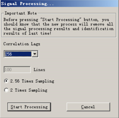
6) Begin signal processing, and set the number of correlation lags:
Usually the lags should be set to 256.
For the multiple-setup case, the references are set automatically. But for the one-setup case, you may asked to select the references manually. All the measurements are selected as references by default. Sometimes this default setting may cause too large calculation workload, and you need select some proper references according to all kinds of factors, such as the structure of test model, the positions of measurement points
In the above dialog, you can select or unselect all by clicking the column header of "Index".
Begin Modal Identification
The modal identification procedure is the same as EMA BroBand.


