NVGate Virtual Input
Virtual Inputs
The virtual inputs consist of an intermediate processing stage inserted between the front end and the analyses. Each inputs (or player tracks) can be drag& dropped to the virtual inputs plug-in. A virtual input (i.e. the result of calculation between inputs called Operators) is generated as a standard input. It can be used in the following processes:
- Plug-in analyzers (FFTx, SOA,x, 1/n OCT, TDA, etc..)
- Recording
- Monitoring
- Triggering
- Output generators
The active Operator are made available in the connection trees (i.e. the signal distribution dialog boxes from the Acquisition tab) for a standard use. Signals Operators are 100% in phase with the front end inputs or player tracks.
This structure allows multiple formulas to be applied, such as:
Channel
Each channel represents an operand for the operators. Each channel applies a polynomial
to the input signal and a filtering.
- Source: input source to be process. It may come from the input Front-end or from the Player in the post analysis mode (see the post analysis chapter).
- Input filter: filter to be used for filtering the source before analysis. The Filters that are not compatible with the Front-end range cannot be selected (see the Filter builder chapter). The A and C weighting on time domain are available.
For filter characteristics, see the Appendix.
- Coef: This value is multiplied with each sample of the incoming signal (source setting). Any real value (i.e: -5.334). The Coef is the A member in the following formula :
- Offset: This value is added to each sample of the incoming signal (after applying the coef). Any real value (i.e: -1.5 E-3). The Offset is the B member in the following formula : (A*i+B)P
- Power: This value is used to power with each sample of the incoming signal (after applying the coef and the offset).
Operators
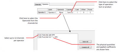
The Virtual inputs plug-in generates signals from operators. The operator gathers the polynomial member in one signal. There are 12 operators available.
- Label: Used to identify the results from the operator. The operator label is used in place of the input label.
- Sources: The list of operand to be used by the operator. The operands are selected from the Virtual Inputs active channels. Up to 12 channels can be used in one operator.
Operator: The operation between the channels. There are 2 different operators;
- Coef: This value is multiplied with each sample of the outcoming signal. Any real value (i.e: -5.334). The Coef is the A member in the following formula : (A*Op+B)P
- Offset: This value is added to each sample of the outcoming signal (after applying the coef). Any real value (i.e: -1.5 E-3). The Offset is the B member in the following formula : (A*Op+B)P
- Power: This value is used to power each sample of the outcoming signal (after applying the coef and the offset).
Note: if the software is able to solve the dimension formula between the channels and the operator (including the coef/offset/power), the output magnitude will be automatically applied. If not, the output will be proposed in Volts.
Twist
The twist measurement consists of computing the angle between the 2 side of transmission shaft (or belt/chain). The measured angle is directly proportional to the stress and the applied torque.
The twist can be:
- Static twist: measure the transmitted torque and power. This is a parameter, not for analysis purpose
- Dynamic twist: measure the oscillating stress and resonances. This is a dynamic signal to be analyzed.
Both signals (torsional) are computed simultaneously by the virtual input module.
For computing the phase between the 2 sides of the twist it is necessary having a tachometer.
This tachometer can come from any of the inputs or directly from one of the torsional signals using the Torsional + tach. mode.
The Twist sub-modules allow selecting each torsional signal from the source 1 and source 2 lists.
The twist will be displayed in angle or torque. The coefficient is used to convert the read angle in torque.
The result are available from the add/Remove windows under the virtual input tab.
Note that any number of pulses/rev can be used for twist computation and these numbers of pulses/rev can either be different on each side.
Tutorial
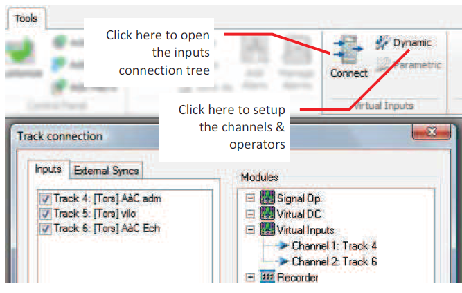
First connect the tracks on virtual inputs plug in..
For each channel, you can aplly this equation :
On operator tab you can sum or multiply the channels , then aplly a new equation.

]
Virtual DC
The Virtual DC plug-in allows mixing any parametric inputs (universal, DC or Aux. DC) together in order to generate internal signal used for:
- Recording
- Monitoring (view meter – profiles)
- Triggering: Level/Delta Level
- Waterfall references (Z/X axis)
- Tachometer (DC Tach)
Channel
The DC channels must be connected to the Virtual DC plug-in before using it in an operator:
- Source: input source to be process. It may come from the DC Front-end or from the Player DC tracks in the post analysis mode (see the post analysis chapter).
Operators
The Virtual DC plug-in generates signals from operators. The operators compute the channels sample in one signal. There are 12 operators available.
- Label: Used to identify the results from the operator. The operator label is used in place of the input label.
- Physical quantity: Define the output signal physical quantity. This setting is not automatic it must be set by the user. The software does not check the dimension equation of the generated signal.
- Equation: editor for the math formula to compute. The result of the last line of the editor is the signal generated by the operator.
Formula editor
The formula editor accepts various math operators and functions such as square root, logarithms and power allowing polynomial equations. The following table gives the syntax of the operators and functions;
| In/out | Description |
| Chi | Channel i level |
| N.A. | The output level is the result of the last line in the editor |
| Operator | Description |
| + | Parameter or constant addition with another parameter or constant |
| - | Parameter or constant subtraction from another parameter or constant |
| * |
Parameter or constant multiplication by another parameter or constant |
| / | Parameter or constant division by another parameter or constant |
| ^ | Parameter or constant powered by another parameter or constant |
| = | Parameter affectation with the expression result at the right of sign |
| Function | Description |
| If(c, t, f) | Returns t if c is true or f if c is false (ex of c: I >4) |
| Rint(x) | Returns the nearest integer of x |
| Sign(x) | Returns -1 if x < 0, 0 if x = 0 or 1 if x > 0 |
| Function | Description |
| Sin(x) | Returns the sine of expression or parameter x |
| Cos(x) | Returns the cosine of expression or parameter x |
| Tan(x) | Returns the tangent of expression or parameter x |
| ASin(x) | Returns the arc sine of expression or parameter x |
| ACos(x) | Returns the arc cosine of expression or parameter x |
| ATan(x) | Returns the arc tangent of expression or parameter x |
| Sinh(x) | Returns the hyperbolic sine of expression or parameter x |
| Cosh(x) | Returns the hyperbolic cosine of expression or parameter x |
| Tanh(x) | Returns the hyperbolic tangent of expression or parameter x |
| ASinh(x) | Returns the hyperbolic arc sine of expression or parameter x |
| ACosh(x) | Returns the hyperbolic arc cosine of expression or parameter x |
| ATanh(x) | Returns the hyperbolic arc tangent of expression or parameter x |
| Log2(x) | Returns the base 2 logarithm of expression or parameter x |
| Log10(x) | Returns the base 10 logarithm of expression or parameter x |
| Log(x) | Returns the base 10 logarithm of expression or parameter x |
| Ln(x) | Returns the base e (natural) logarithm of expression or parameter x |
| Exp(x) | Returns the exponential of expression or parameter x |
| Sqrt(x) | Returns the square root of expression or parameter x |
| Abs(x) | Returns the absolute value of expression or parameter x |
| Min(x,y,…) | Returns the minimum level of listed parameters |
| Max(x,y,…) | Returns the minimum level of listed parameters |
| Sum(x,y,…) | Returns the sum of listed parameters |
| Avg(x,y,…) | Returns the average level of listed parameters |
| Predefined | Description |
| pi | Constant pi (3.1416…). Do not declare any constant with this name |
| e | Constant e (2.718). Do not declare any constant with this name |
Constants and parameters can be defined (except pi and e) using the = sign; eg: var1 = pi * 2 or var2 = rpm1/2. The constants may be defined once only.
Parameter/constant names must start with a letter and may be ended by a number. The dot (.) is always the decimal separator independently from the OS preferences and the comma (,) is used as parameter separator.
The editor does not check the dimension of this result. The content of the formula can be copy/paste from any text editor.
- Valid: Indicates if the operator valid or not. To be valid an operator must process one of the virtual DC channel in its equation
- Min output / Max output: define the output range. These settings are expressed in the unit of the selected magnitude of the operator.
Tutorial
First connect the DC channels to the virtual DC plug in.
A new track "operator 1" is now create and appear on channels connection. You can use it as any other DC input.


