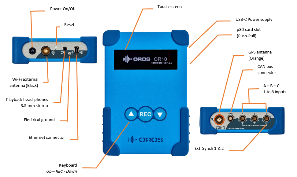
OR10 MODS
OR10
Package contents
Your OR10 is delivered with accessories, software and licenses according to the ordered configuration.
1.
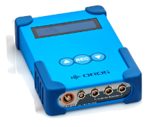
OR10 Instrument, with 4 or 8 dynamic inputs, 2 ext. sync inputs and optional software licenses for NVGo android App, Standalone interface and NVGate PC software
2. USB-C power supply designed to power OR10, and charge internal battery.
3. USB-C cable for power supply.
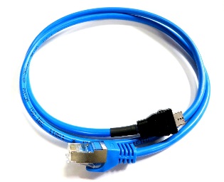
4. Specific Ethernet cable for operating OR10 from PC with NVGate software.
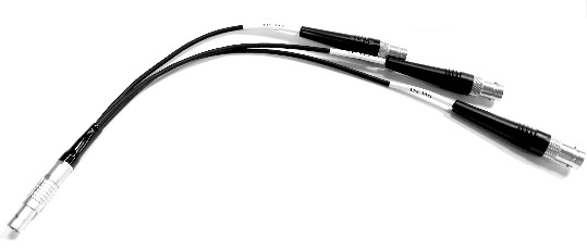
5. Lemo to BNC adapters cables: 3 models:
A: Dynamic inputs 1 to 3
- B: Dynamic inputs 4 to 6
- C: Dynamic inputs 7 & 8 plus Ext. Sync 1 & 2. Input 8 and Ext. Sync 1 are sharing the same BNC.
Note: these mini-LEMO connectors are spring locked. Pull-on outer ring to remove the connector.
6. GPS antenna.
7.
External Wi-Fi antenna to extend wireless range. Works for both NVGo Apps on tablet or smartphone and NVGate on PC.
8. CAN bus cable (Optional)
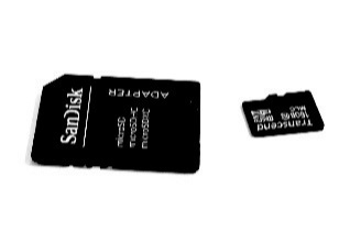
9. µSD card adapter for PC.
Carrying bag. 3 pouches:
- Central is for the OR10 instrument.
- Mobile is for the field accessories (BNC adapters, antennas, USB cable for power bank) usage. This pouch is also suitable for carrying transducers.
- Office is for stationary accessories: Power supply, Ethernet cable, USB cable and µSD card adapter.
NB: The carrying bag may be disassembled in order to:
- Adjust form factor (Flat) to travel luggage
- Reduce size by leaving accessory pouch when it is not required (ex: Office for field measurement)
Pouches are maintained together by magnetic & locked fixtures. Lift up lateral pouches to detach. Affix pouches laterally to attach.
====Instrument description
Starting OR10
Connect the USB-C cable to the OR10 on one side and to the power supply on other side. Plug the power supply into the mains. The OR10 beeps 2 times to acknowledge power supply presence.
How to use the touch screen
The OR10 touch screen does not react to short Presss. Use longer press (200 ms to 0.5 second) for proper operations with the touch screen. The top and bottom arrows on the screen can be pressed from the keyboard.
==
Powering on/Off==== Press the On/Off button from Top panel until OR10 beeps. The instrument shows the following screen:
If you power-on the OR10 in battery mode (No USB-C power supply), the system requires confirmation<ref>This behavior is compulsory for shipping devices with Li-Ion batteries by Airplane.</ref>. Press Yes or down arrow to start.
The system shows the serial number and the middleware version.
If you have a standalone license it is replaced by the following one:
Your OR10 is now ready to be operated with the purchased licenses.
To power off the OR10, Press the On/Off button:
One time shortly, the screen will offer: Press on Shutdown to power off.
- Maintain the pressure until the OR10 rings. OR10 shutdowns just after pressure release.
Connecting to OR10
To PC through Ethernet<ref>The OR10 Wi-Fi is automatically disabled when the OR10 is connected to NVGate with the Ethernet cable.</ref>
Connect the delivered Ethernet cable between the OR10 and the PC. The Ethernet protocol used by OR10 is IP V6. Check that your PC's Ethernet adaptor is properly configured for IPV6 connection. IP addresses are automatically managed.
To PC or Tablet through Wi-Fi
Attention, NVGate is a real-time software which need to process gap free signal (no missing samples). OR10 being a DAQ, it sends continuously raw data to the PC. Using Wi-Fi connection is not recommended in buried environments or with high channel * sampling frequency configuration. Using a wired Ethernet ensures gap free acquisition and stable operations
Enable and setup OR10's access point
Verify the OR10 Wi-Fi is activated from the following menu on the instrument.
Press the instrument menu on top left of main screen. Then press the Wi-Fi button, the Wi-Fi menu is displayed.
Enable the Wi-Fi and install the Wi-Fi antenna (black) on the top of OR10.
Caution, do not invert the Wi-Fi (Black) and GPS (Orange) antenna. This may break the connectors pin.
Bandwidths and locations must be adapted to the country where you operate wirelessly the OR10.
Bandwidths: Pressing the top right button toggle the bandwidths between n / 2.4 GHz and ac / 5 GHz.
Locations: the location is adjusted from the NVGate Connection dialog. This usage does not require licenses.
Caution: the 5 GHz bandwidth is not compatible with World location. Selecting this combination from OR10 screen will block the OR10 Wi-Fi.
Connect to the access point
The Ethernet protocol used by OR10 is IP V6. Check that your PC's Ethernet adaptor is properly configured for IPV6 connection. IP addresses are automatically managed.
Open the wireless connection dialog and select the OR10. Your OR10 SSID is: OR10_XXXXXX where XXXXXX is your OR10 S/N.
A password is requested. Default password is "12345678". It is recommended to update this password to ensure data security and avoid interferences or malwares.
Start NVGate from the PC. No licenses are requested at this point. The NVGate connection window in displayed:
If your instrument is not visible, click on Refresh to update the list. with Windows 10, if the OR10 is not visible, it may be necessary to allow "Manage random addresses" from the OR10 Wi-Fi connection properties.
Select the instrument, the right panel will show OR10 information. Hyperlinks allow modifying contents/settings.
For Wi-Fi setup, click on Server, the IP dialog is displayed.
Mode and Country must be adjusted to local standards.
Channel allows optimizing the Wi-Fi performances and bandwidth jamming. Available channels depend on selected Country. Contact your IT services to adjust it.
It is recommended to modify the default password.
Your OR10 is now connected to the PC within local regulation standards. Click on Ok and on Start from the NVGate connection dialog to launch NVGate software with the OR10 as a front-end.
Accessing OR10 data
OR10 data consist of Templates (setups) and Measurements saved in the µSD memory.
Using the µSD card adapter
Press the instrument menu on top left of main screen. Then, press Swap SD button.
The swap procedure starts, it takes just a few seconds:
1. When the OR10 asks: Swap SD card? press Yes to continue
2. Then OR10 proposes: Remove and insert new SD card. Remove the µSD card from the chassis aperture on the right side of the OR10 by push-pulling the card on the slot.
3. Plug the µSD in the adapter and plug it to the PC.
4. Browse the SD card from your PC. Files & directories are available for Copy/Paste/Delete. Directories and files types are discussed in next chapters.
5. When your data are collected, re-plug the µSD car into the OR10 slot, and press Done to continue.
OR10 restarts. It will be ready to operates when the Main menu of the standalone interface is shown.
6.
Standalone operations
Template preparation
Standalone operations with OR10 are conducted with the OR10's keyboard and touch screen. It features simple and fast setup and data acquisition with reduced interface. In order to benefit from the various OROS instruments possibilities, it is recommended to use predefined templates. Templates applies multiple front-end and recorder setups to OR10 in standalone operations.
Templates are generated by NVGate the OROS Software platform<ref>It is also possible to generate Templates by editing files manually. It is not recommended to use this manner as the format may change without notice.</ref>. Templates are transferred in the OR10 memory in 2 possible ways:
- Directly when NVGate running in connected<ref>Any OROS instrument license can be used to prepare templates. License input number may limit templates inputs number.</ref> mode on the OR10<ref>Optional instrument locked NVGate license required.</ref> by
- Ethernet cable
- Wi-Fi
- By file transfer from PC to µSD card
NVGate Template generation
This feature is available from NVGate version 11.30.
1. Launches NVGate on the PC with your license:
- Dongle locked: Plug the delivered OROS dongle in one of the USB port of the PC running NVGate.
- Instrument locked: Connect the OR10 to the PC (Ethernet or Wi-Fi) to the PC.
2. Setup the front-end:
- Inputs & Ext. sync activation, couplings, sensitivities, ranges, labels, thresholds
- Sampling frequency. Note: the highest SF will be applied to all inputs
- CAN bus channels (up to 16) & parameters
- Recorder setup, duration and type (Start to stop and Start to time only)
3. Add the setup to the OR10 or to file:
- Click on Home/OR10 Setup/Add current.
- The Template setup dialog is displayed
OROS NVGate software uses DataSet Management (DSM) native technology. DSM features flexible properties that inform the used and produced data. (see M002-115-7 Users' manual for details).
MODS Templates benefit from this technology. The Template Setup dialog allow adding/editing comments and properties to the Templates and Measurements as follow:
- Description will be showed with the Template name into Standalone and NVGo interfaces,
- Template properties will be showed with the Template name & description into NVGo interface. The properties will be added to all Measurements made with this Template,
- Measurement properties will be showed for edition while saving measurement into NVGo interface,
- When importing measurement files in NVGate, the properties the destination Project will be added to all imported Measurements.
Adding Template by files
When Templates are generated without OR10 connected to the PC (Dongle locked or Instrument locked on another OROS instrument) the transfer is made by file copy.
Click on the "Add to folder" button on bottom of the Template Setup dialog. Browse to the OR10 µSD card.
Open Data\template and click on Select Folder. Your new template is now available from OR10.
Standalone acquisition
In standalone mode the OR10 instrument operates autonomously being setup through the keyboard and touch screen. Standalone mode requires an instrument locked license to operate.
The sequence of operations is as follow
1. From the main screen, browse and select the appropriate Template:
2. Press down arrow to apply chosen Template to OR10 front-end. The input load is shown.
Note: Keyboard arrows may be used instead of touch screen ones.
3. Press the top left menu to adjust and check front-end with:
- Playback: play the inputs signal to the headphone connectors in stereo. Inputs are routed/un-routed to left or right channel by pressing the inputs position on the screen.
To move to another input, first un-route the input already routed to L or R channel. Playback volume can be adjusted by pressing the top right loudspeaker icon.
- Auto Range: Adjust individually and synchronously each input range according to the max absolute level on 1 sec period.
- Check ICP: Check the presence of an ICP transducer on each input. This takes few seconds to stabilize the ICP voltage.
- CAN: Show the number of CAN messages configured and acquired.
- GPS: Enable/Disable the GPS. Provides status, position and number of satellites. Note: The GPS antenna provides best results while being set horizontally.
4. Check available memory…
5. tart acquisition: Press REC button on the keyboard. Status switches to Recording<ref>during the recording, Auto Range and Check ICP functions are disabled.</ref> and duration is displayed. All active inputs and CAN channels are recorded.
6. Stop the acquisition: The acquisition stops
- At the end of the defined duration in Start to Time mode,
- When REC button is pressed.
7. Save the record: Records are saved with the predefined base name of the used Template. A combination of a 3-digit number and a letter is added to manage the multiple acquisitions:
- Letter is incremented while using the same Template for multiple acquisitions
- Number is incremented and letter reset when Template is changed.
- Number and letter are adjusted to follow the highest file name combination on the OR10 memory.
All the properties with contents are saved with the recorded data. Saved properties will be associated to the Measurement when records are imported in NVGate.
8. Make a new acquisition or restart from point 1. Press up arrow to return to main screen.
Recovering recorded files from OR10
Recorded data are saved in OROS proprietary format. Those files must be imported in the OROS NVGate software platform prior to post-analysis or export to other formats.
Connect the PC OR10 memory to the PC (see § Accessing OR10 data) and start NVGate on the PC. From NVGate ribbon click on Home/Dataset/Import.
The import file dialog is opened.
- Select file type: OR10 signal (.or10),
- Select destination Project. Note the imported record files will be will be added to this Project as Measurements. The Project properties will be added to the Measurements,
- Select source path, OR10 or folder (see § Accessing OR10 data),
- Sort and Select the set of files to import,
- Click on Ok, your files are now available in the NVGate data. These files are compatible with all modules of the OROS software suite.
GPS files
When the GPS is activated and see satellites, the successive (3D, 10 Hz) positions during the record are saved with the signal. GPS data are imported with the signal as .gpx files. These files are stored in the "Attachment" directory in the imported measures. From NVGate interface, open the project manager (Home/Workflow, then Project manager). Right click on the imported Measure and select Attachement.
Post-process OR10 data
From this point, recorded data may be:
- Post-analyzed with NVGate plug-ins or other modules of the OROS software suite,
- Exported (.txt, .uff, .wav) to others software according to the NVGate export licenses (.sdf, .atfx),
Directly processed by 3rd party software compatible with NVGate formats (OROS SQ, MODAL.)
NVGo
NVGo is the MODS monitoring software for android devices. This app is designed to:
- Manage Templates for OR10 front-end and record setup,
- Adjust the front-end and recorder settings
- Continuously monitor the signals in different domains (level, time and spectral),
- Start & stop recording,
- Add properties and comments to records,
- Manage records in OR10 memory.
Installation
1. Register on www.myOROS.com
2. From the Software section select NVGo -> Latest software
3. Download the latest NVGo Android Package Kit (.APK) on your Tablet or smartphone.
4. On your Android device open download section and select the NVGo .apk file, then choose install
5. Authorize the installation of unknown sources for once as OROS does not use Google play store for its software broadcasts.
Connection to OR10
1. Start NVGo from the Android device.
2. Power on the OR10 hardware
3. Wait for power-on until you get the main menu on the OR10 screen
4. Press "Wi-Fi" button on NVGo. The Android Wi-Fi menu is displayed
5. Connect to the OR10.
6. Press Android back () button to return in NVGo.
Refresh the instrument list. When your OR10 appears showing "Ready" Press on it to start NVGo with this instrument.
| Main screen |
LiveView
LiveView screen shows the spectra and trigger blocks of the 2 highlighted inputs of the left column.
Displayed inputs are changed by swiping the graph up/down. It is also possible to select the displayed inputs by Pressping the selected input from the left column.
FFT settings allows adjusting averaging and resolution. Y scale may be set to linear or log. This preference is memorized in the Android device.
Signal
Signal shows the raw data envelope of the 2 highlighted inputs of the left column.
Displayed inputs are changed by swiping the graph up/down. It is also possible to select the displayed inputs by Pressping the selected input from the left column.
Y scale is continuously adjusted to input ranges. When the 2 active inputs show the same units, both Y scales are identical.
Levels
Levels shows the RMS and Peak levels of all dynamic inputs together.
Playback
Press the headphone icon on bottom right of the main screen to activate the playback. The 2 active inputs (blue background on the Signal and LiveView screens) are replayed on the OR10 headphone plug. The volume is automatically adjusted.
Caution, the playback volume is dependent on the used headphone impedance. Signal amplitudes close to the range peak may generate high volume with low impedance headphone. Usage of very low impedance below 60 Ohms is not recommended. The stereo allocation of the played signals may be inverted by pressing the headphone button until the 2 background colors are inverted.
Setting up OR10
Load a Template
The Templates are generated and added to the OR10 memory with NVGate (see NVGate Template generation §). They are used in the same way as NVGate Models to setup the front-end with predefined settings. The Template properties and description will be saved in the Measurements made with it.
Press the central (Setup) field of the top ribbon to open the Template selection screen.
Adjust the Front-enD
Inputs settings may be adjusted manually. Press the left (Settings) BNC button of the top ribbon to open the Front-end settings screen.
Adjust the sampling frequency
The sampling frequency is always displayed in the main screen. Simply select the desired sampling rate from the Top ribbon drop down menu.
This menu is not available when the OR10 is recording.
Adjust the recorder
The recorder mode and duration may be adjusted. Press the left (Settings) Presse recorder button of the top ribbon to open the Recorder settings screen. This menu is not available when the OR10 is recording.
Select recorder mode between fixed duration Start to time and manually controlled Start to Stop.
For Start to time the duration should be updated by editing the field or using the +/- buttons.
Make a recording
Start recording
When the OR10 setup is done, the system is ready for start acquiring and saving the input data. To start the recording, Press on the bottom left Run button or press the REC button on OR10.
To stop the recording, Press on the bottom left Stop button or press the REC button on OR10. In Start to Time mode, the record will stop automatically, when duration time is reached.
Save & inform recorded data
When the record is finished, the save screen is shown.
Recordings are saved with the predefined base name of the used Template. A combination of a 3 digits number and a letter is added to manage the multi-acquisitions:
- Letter is incremented while using the same Template for multiple acquisitions (called RUNs)
- Number is incremented and letter reset when Template is changed.
- Number and letter are automatically incremented to avoid overwriting existing files in the OR10 memory.
In that way, each RUN of a measurement type will be called: BaseName_102A, BaseName_102B, BaseName_102C, etc…
All the properties with contents are saved with the recorded data. Saved properties will be associated to the Measurement when records are imported in NVGate.
Check OR10 memory content
The OR10 recorded data may be browsed from NVGo. Press on the Capacity field (DAQ) from the Top ribbon right.
The Record list screen is displayed
<references/>

