ORBIGate DemoData
How to demonstrate ORBIGate 6 :
Introduction
This document shows a way to demonstrate the main features of ORBIGate 6.x through a scenario. The used data come from measurements on a rotor kit equipped with fluid bearings.
The data contain 2 major issues:
- Oil Instability causing subharmonic phenomenon
- Critical speed causing large orbit
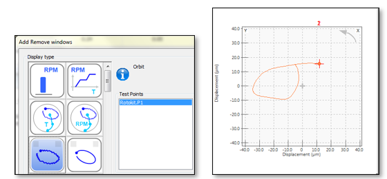
To display result, use this icon:
Instructions
Oil instability diagnostic
- In File tab, "load measurement", select the demo_rotokit_OROS.obg
- Add/Remove result window to display :
- Speed profile
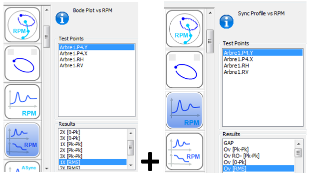
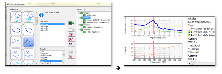
- Bode Plot vs RPM of 1X [RMS] overlaid by profile OVL [RMS] vs RPM
For a good health machine, 1X should be overlaid with Overall because there is only imbalance.
However there is a speed range while overall level is higher than 1X level.
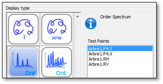
- To investigate what orders (in addition to 1X) are carrying energy in this speed range, let's display the synch spectrum:
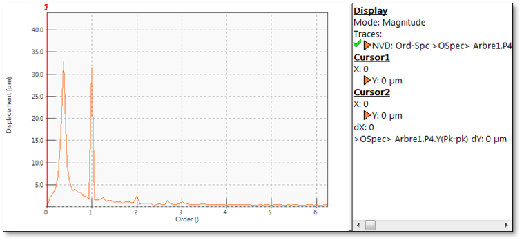
- Place navigation cursor in the speed range of interest and look at the synch order spectrum:
- Subharmonic issue occurs in this speed range
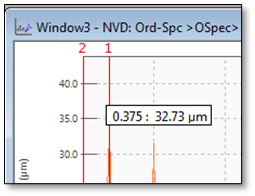
- Place windows cursor in the order spectrum to know which is subharmonic order
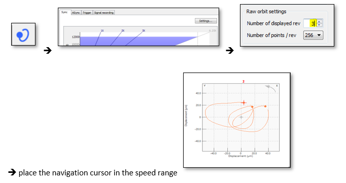
- 0.375 order means the issue cycle is completed roughly each 3 revolutions, so it could be helpful to display orbits (3 displayed revolutions)
- First, display raw orbit
- Then, change analysis settings to display 3 orbits
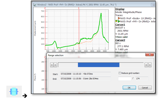
- To generate report for this first issue, let's hide the second issue (critical speed). So let's focus on data related to oil instability. Select the data range of interest (with the mouse on the blue bar)
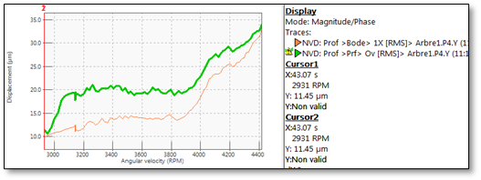
- Then the bode plot looks like this view:
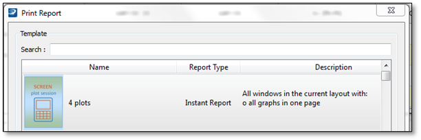
- Place the cursor to display relevant result and generate a report:
Critical speed
Let's focus now at the critical speed to know the frequency of the first bending shaft mode and the orbit size at this frequency
- Change the data around the critical speed
- Add Smax (orbit size) to the window2 so that the SMAX is display with 1X and Overall
- Place the cursor at the critical speed and generate a new report
Shaft center line
How to display the shaft center line and use the GAP reference:
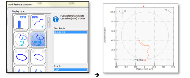
- Display the shaftcenter line:
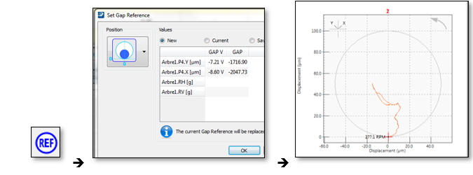
- The shaft centerline is not perfectly starting from the clearance circle, so we need to reset the gap reference at the lowest speed (when the shaft is assumed to lay at the bearing bottom).
- Select the lowest speed with the navigation cursor and press on GAP reference:
The shaft center line is now starting at the bottom of the clearance circle
All this demo have been done in the navigation mode, no need to post-analyze signal, all results are saved during the measurement !
