Difference between revisions of "OR3X Hardware Instruments"
| Line 16: | Line 16: | ||
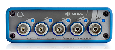
O4 is a compact analyzer. It offers 2 or 4 dynamic inputs with 2 ext. sync and 1 generator. | O4 is a compact analyzer. It offers 2 or 4 dynamic inputs with 2 ext. sync and 1 generator. | ||
[[Image: | [[Image:O4.png|framed|none]] | ||
====Back Panel==== | ====Back Panel==== | ||
Revision as of 15:37, 3 March 2023
OROS Teamwork instruments Range
This manual applies to the whole OROS Teamwork instruments range.
Dear customer, thank you for purchasing an OROS Teamwork instrument. The Teamwork instruments are designed to fulfill industrial applications of noise and vibration measurement and analysis.
Your new instrument covers most of the measurement situations in the Automotive, Manufacturing and automation, Energy & Process, Aerospace and Marine industries. It applies for real-time/Post-analyses as well as recording/playback of a raw signal.
These instruments are suitable for field, on board and laboratory operations. They are also capable of remote/standalone measurements without any operator at their side.
OROS Teamwork analyzers mainly run while connected to a Windows PC that drives the control and analysis software.
OR4 analyzer
O4 is a compact analyzer. It offers 2 or 4 dynamic inputs with 2 ext. sync and 1 generator.
Back Panel
The back panel includes:
- Ethernet connector: RJ-45 connector, Network environment 100 Mbps (100 BASE-TX), cable required Category 5 unshielded twisted-pair
- Interface connector: RJ-11 for remote control and maintenance
- DC power connector: Connector DIN female
DC power supply
The DC power must fulfill the following conditions:
| Voltage | OR34 Power |
Overload action |
| DC, 10 V to 28 V | >15 VA | + and – poles are short circuited if Vpeak > 31 V |
OR34 instrument is DC power supplied using the following plug:
All the connections of OR34 instruments comply with SELV (Safety Extra Low Voltage) conditions.
OR34 Powering on
A beep is produced when the instrument is connected to the mains.
Power on OR34 Instrument by pressing the On/Off button of the back panel and wait until a beep is produced (2 sec) then release the button. The LED is fast flashing green (system is loading) and then slow flashing green (system OK).
Power off OR34 Instrument by pressing the On/Off button of the back panel (The LED is flashing red) Then wait until a beep is produced (2 sec) to release the button.
If OR34 Instrument does not respond, unplug the main power supply and press the reset button ![]() (use a paperclip) of the back panel.
(use a paperclip) of the back panel.
OR35/OR36/ORMP/OR38 Teamwork instruments
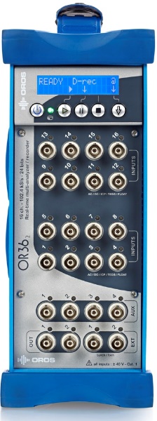
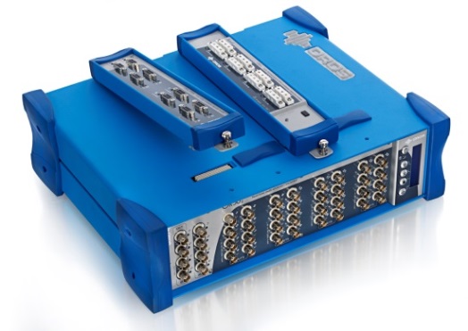
OR35, OR36, ORMP & OR38 cover high end applications with multi-channels chassis. They offer from 4 to 32 universal inputs, 2 ext. synch, 2 generators and optional auxiliary channels supporting generators, trigger/tach and parametric inputs.
Front Panels
| OR38 | OR36/MP | OR35 | |
| Inputs | 1 to 32 Universal | 1 to 16 Universals |
4 or 8 Universal + 2 Dynamic |
| Outputs | Generators 1 & 2 | Generators 1 & 2 | Generators 1 & 2 |
| Triggers | External Sync.1 & 2 | External Sync 1 & 2 | External Sync 1 & 2 in // with Dynamic 9 & 10 |
| Auxiliaries | 4 DC, GEN or Ext synch (Depending on the purchased options) | 4 DC, GEN or Ext synch | No |
| Overview |
The universal inputs gather both dynamics and parametric input in the same board and connectors. The type of use of the universal inputs is selectable by software (NVGate®) during the analyzer operations. The universal inputs fulfill all the performances, precision and operability of each specific input type. All the connections are Very Low Safety Voltage.
Inputs LED colors
For each input connector LED shows the current status:
| Color | Input type | Signal level |
| Green | Dynamic | FS<ref>Full scale</ref>-30 dB < Signal < FS |
| Cyan | Dynamic | 0 < Signal < FS-30 dB |
| Red | Dynamic/Parametric | Signal > FS (Overload) |
| Yellow | Parametric | FS-30 dB < Signal < FS |
| Purple | Parametric | 0 < Signal < FS-30 dB |
| Off | Inactive | N.A. |
Lateral panel
With the universal inputs and the adapted connection kit<ref>Not available for ORMP</ref>, the OR35, OR36 and OR38 can hold signal conditioning modules called XPod (dockable eXPander module).
The XPod is a device that can be fixed on the OR35/OR36/OR38 side. Each XPod is associated to a block of 8 inputs.
The following optional XPod are available:
- Bridge signal conditioning for strain gauges, dynamic pressure and force measurements.
- Thermocouple and RTDs for temperature measurements.
To fix the XPod on the analyzer:
1. Warning: do not plug or unplug the XPod when the analyzer is powered on, shut it down for this operation.
2. Lock the XPod hook in the notch on the back of the analyzer,
3. Lower the XPod to the corresponding connector on the top of the analyzer,
4. Secure the XPod on the analyzer with the screw on the extension key of the XPod
| 1 | 2 | 3 |
|---|---|---|
Note: When travelling, fix the XPod on the analyzer to avoid any damages. When there is no XPod, fix the rubber cover on the analyzer. There are two rubber covers on the XPod which allows having a cover left if one is lost.
Back Panels
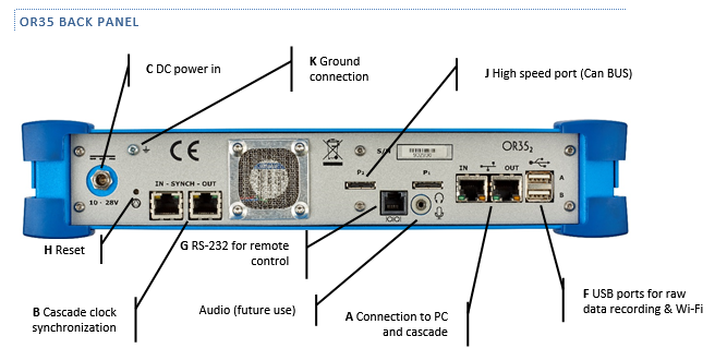
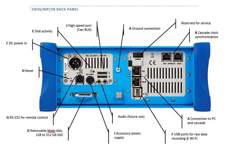
The back panel supports the connectivity, power supply and accessories connections.
OR35 instrument complies with SELV (Safety Extra Low Voltage) conditions.
All the connections of OR36, ORMP and OR38 instruments comply with SELV (Safety Extra Low Voltage) conditions.
Back panel connectors description
- 2 Ethernet (1 Gb/s) connectors for connection to PC and cascade of analyzers.
- Connect the PC to IN
- In cascade mode connect the PC to first analyzer (master) to IN. Next units are daisy chained (OUT -> IN, OUT- > IN, etc…) in cascaded mode.
- Cable required Category 5 unshielded twisted-pair. Use the blue cables.
- 2 clock synchronization connectors (100 Mb/s Ethernet)
- Do not use while using a sole analyzer
- Daisy chain from Master unit to the next one in cascaded mode (OUT -> IN, OUT- > IN, etc…)
- On the Mobi-Pack, synchronization connectors are on the front panel
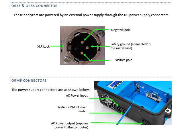
- DC power in XLR connector<ref>Not available on ORMP </ref>. To be plug with the external power supply.
Warning, do not mix the instrument power supply types.
- Mobi-disk. The Mobi-Disk holds the recorded raw data.
, Caution, power off the analyzer prior removing or inserting it.
- When using the analyzer without the Mobi-disk plugged-in, use the obturator cover to protect the internal part of the analyzer
- Disk activity LED. The LED will flash while data are written on or read from the disk.
- USB 2.0 for raw data recording. To record on a external disk, power off the analyzer, remove the Mobi-Disk (put the obturator cover), plug you USB memory device and power on. The raw data will be saved on the memory device.
Caution, the write speed on your memory device may lead to a throughput error, check the performance before using it for actual measurements
- Interface connector: RS-232 for remote control through RJ11 connector
- Reset. To be used when your analyzer does no respond to any command. Insert a paper clip in the hole and press smoothly.
- Accessory Power supply. This connector provides power supply for external use (transducer, tachometer, etc… power supply). The available voltage and power are:
- +5 V, 3 W, 1.6 A
- +9 V, 6 W, 650 mA
- +15 V, 6 W, 25 mA
- High speed port: Used for connection the CAN bus probe
- Ground connection. Use this screw to connect the analyzer to the ground potential
DC Power supply
OR35 connector
OR35 features a coaxial connector. Center is positive terminal; outer ring is negative and ground terminal:
The analyzers may be powered from an external DC voltage6 to replace the external power supply. The power voltage and current must fulfill the following conditions:
OR35 Power supply
| Power | < 30 VA | |
| External AC Power supply | Voltage | 110 to 220 VAC 1.7 A max |
| Frequency | 50/60 Hz | |
| DC in | Range | 10 V to 28 V |
| Overload protection | Absolute maximum < 40 V / > 31 V poles are disconnected | |
| Battery | Type | Built-in 89 Wh Li-ion 8 modules (UN38.3 certified) |
| Autonomy | 3 h (4 ch 1 DSP 12.8 kS/s) | |
| Charge time | 3 h (typical) | |
| Charge conditions | DC power supply > 12V | |
OR36/ORMP Power supply
| Power | < 60 VA | |
| External AC Power supply | Voltage | 110 to 220 VAC / 1.7 A max |
| Frequency | 50/60 Hz | |
| DC in (Not applicable to the ORMP) | Range | 12 V to 28 V (DC voltage < 17 V will discard the battery) |
| Overload protection | 31 V (over this voltage DC poles are short-circuited) | |
| Battery | Type | NiMh 11 modules (no memory effect) |
| Autonomy | 2 h (4 ch 1 DSP 12.8 kS/s) | |
| Charge time | 2 h 30 min (typical) | |
| Charge conditions | DC power supply > 18 V | |
OR38 power supply
| Power | < 100 VA | |
| External AC Power supply | Voltage | 110 to 220 VAC / 2.0 A max |
| Frequency | 50/60 Hz | |
| DC in | Range | 15 V to 28 V (DC voltage < 22 V will discard the battery) |
| Overload protection | 31 V (over this voltage DC poles are short-circuited) | |
| Battery | Type | NiMh 17 modules (no memory effect) |
| Autonomy | 2 h (8 ch 1 DSP 12.8 kS/s) | |
| Charge time | 3 h (typical) | |
| Charge conditions | DC power supply > 24 V | |
Note: All External power supplies accept mains supply voltage fluctuations up to ±10 % of the nominal voltage; Transient overvoltage up to the levels of Cat II; Temporary overvoltage occurring on the mains power supply.
Note: Externals power supplies provided by OROS must operate in the range of -10°C to +40 °C
Batteries
OROS Teamwork instruments contains an internal battery block particularly useful for autonomous operations (except for OR34) or in case of temporary power failure (all OROS Teamwork instruments).
The batteries of OROS Teamwork instruments are designed to provide maximum trouble-free life. To obtain the longest battery life, please follow the following advice:
- Caution: Temperature above normal room temperature will shorten battery life. If OROS Teamwork instruments is stored or shipped at more than 40°C (104°F), recharge it before running the system.
- Charge the battery in cool area. The battery is charging when an OROS Teamwork instrument is plugged to a power supply. Charge stops when the Front Panel indicates 100%.
- Caution: Never store OROS Teamwork instruments with a discharged battery.
All batteries gradually lose their charge (the higher the temperature is, the quicker the batteries lose their charge). If you store your system for a long time without using it, recharge the batteries every two or three months. This practice will extend battery life.
Fan
The cooling fan is used to reduce the temperature inside OROS Teamwork instruments. From the Front Panel the user can manually switch it on or switch off (for very sensitive acoustic measurements).
The fan operation will be automatically forced when the temperature inside the OROS Teamwork instruments reaches 50°C and stops at 43°C.
Warning: Do not cover the Teamwork instrument in order to let the ventilation operate properly.
Temperature and fan management
| Internal temp | System status | Fan |
| 70°C (158 °F) | Absolute maximum rating | Off |
| 65°C (149 °F) | Forced shutdown, do not operate | Off |
| 60°C (140 °F) | Normal | Forced max |
| 50°C (122 °F) | Normal | Automatic Fast |
| 45°C (113 °F) | ||
| 40°C (104 °F) | Normal | Automatic Slow |
| 35°C (95 °F) | ||
| 30°C (86 °F) | Normal | Off |
| 0°C (32 °F) | ||
| -5°C (23 °F) | OK with 1 min/°C Warmup | Off |
| -20°C (-4 °F) | ||
| -25°C (-13 °F) | Storage, do not operate | Off |
| -35°C (-31 °F) | Absolute minimum rating | Off |
Powering on/off OR35- OR36/ORMP - OR38
The Teamwork instrument feature an LCD screen on the front panel.
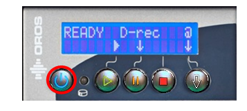
To start OR35/OR36/ORMP/OR38 instruments, press the On/Off button of the Front Panel. "OROS-3 Series Powering up" is displayed on the LCD screen.
Instrument auto-tests are performed until "System OK " appears on the screen or "Ready D-rec" if the D-rec option is available.
If auto-tests return an error message, please contact your OROS Support.
Power off OR35/OR36/ORMP/OR38 instruments by pressing on the On/Off button of the front panel for a few seconds until "Shutdown" appears on the screen or by pressing on the right-hand button of the front panel «", then on the second button for "S" (Shutdown) and confirm by pressing "Y" (Yes).
From the LCD screen:
Press the right-hand button for "". The following menu is displayed:
This menu allows to:
- shutdown the analyzer (second button for "S")
- reset the analyzer (third button for "R")
- go back to the first menu (fourth button for "").
Answer "Y" for Yes
If Instrument does not respond, press the On/Off button until it turns off. Then, power it on again after a few minutes.

