Difference between revisions of "NVGate Monitor Plug In"
Jump to navigation
Jump to search
(Created page with "====Monitor==== The Monitor input can be connected and hot swapped independently of any plug-in analysis. It is used to monitor one or several signals. Image:Waterfall_moni...") |
|||
| Line 44: | Line 44: | ||
* '''High cut-off frequency''': the high cut-off frequency of the filter. Its maximum value is the input frequency range. However, the following conditions must also be fulfilled: see Low cut-off frequency. | * '''High cut-off frequency''': the high cut-off frequency of the filter. Its maximum value is the input frequency range. However, the following conditions must also be fulfilled: see Low cut-off frequency. | ||
* '''Filter''': On / Off. The filter is not applied if '''Filter''' is Off | * '''Filter''': On / Off. The filter is not applied if '''Filter''' is Off | ||
Revision as of 18:23, 19 April 2020
Monitor
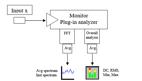
The Monitor input can be connected and hot swapped independently of any plug-in analysis. It is used to monitor one or several signals.
Available results:
- Triggered block: This displays the time domain signal.
- Inst. spectrum: It displays the FFT processing results.
- Avg. spectrum: It displays the average spectrum.
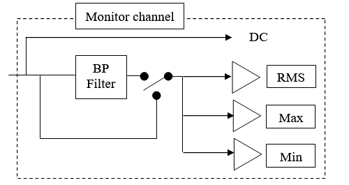
- DC, Max, Min, RMS, Kurtosis on a specified band
Channel
Contains the source of the signal to be monitored.
- Source<ref>Using input 5 to input 8 as source with an OR35 analyzer will cause Non-real-time analysis. This way may lose some trigger event samples.</ref>: input source to be analyzed. It may come from the Front-end input or from the Player in post analysis mode (see the post analysis chapter). In post analysis mode, tracks with a signal bandwidth lower than the range of the Monitor cannot be plugged.
FFT analysis
Contains the settings related to the FFT analysis of the signals to be monitored.
- Range: the frequency range of the Monitor plug in.
Hidden/fixed: The monitor range is fixed by the input frequency range (in connected mode on-line) and by the max bandwidth of the player (in post analysis mode).
- Frequency Span: This is a fixed setting, for information only. It displays the frequency span between two points of a spectral result. The FFT frequency span is obtained by dividing the frequency range of the FFT by the resolution minus 1. For example if the FFT Range is 20kHz and the resolution is 401 lines, then the frequency span is: 20000 / (401 - 1) = 20000 / 400 = 50Hz.
- Resolution: the resolution of the FFT. The FFT frequency span is obtained by dividing the FFT frequency range by the resolution minus 1. For example, if the FFT Range is 20kHz and the resolution is 401 lines, then the frequency span is: 20000 / (401 - 1) = 20000 / 400 = 50Hz.
Hidden/fixed: fixed to 401 lines
- Domain: The averaging domain: spectral domain averaging computes the average after FFT processing.
Hidden/fixed: fixed to spectral
- Avg duration: Exponential coefficient for averaging.
Overall analysis
- Avg duration: Each scalar is computed for each block of signal (length of the block is 256/ (Front-end / Input Sampling), and then average during the value of the setting.
- Filter order: the order of the filter: 2, 4, 6, 8 or 10.
- Low cut-off frequency: the low cut-off frequency of the filter. Its minimum value is 0.055 * FR, where FR is the input frequency range. However, the following conditions must also be fulfilled:
0.0075 * FR <= B <= 0.5 FR,
Where B is the bandwidth between Low and high cut-off frequency
and FR is the input frequency range.
- High cut-off frequency: the high cut-off frequency of the filter. Its maximum value is the input frequency range. However, the following conditions must also be fulfilled: see Low cut-off frequency.
- Filter: On / Off. The filter is not applied if Filter is Off

