Difference between revisions of "NVGate X-Pod: Temperature probe conditioner"
| (40 intermediate revisions by 2 users not shown) | |||
| Line 1: | Line 1: | ||
[[category:NVGate]] | |||
[[category:WikiOros]] | |||
This Xpod handles [https://en.wikipedia.org/wiki/Thermocouple thermocouples] and [https://en.wikipedia.org/wiki/Resistance_thermometer RTD transducers]. | |||
[[File:Xpod_temp.png|framed|none]] | |||
* '''PT100, PT1000 and J, K, T, N, E''' | |||
* Integrated '''linearization''' | |||
* Automatic '''cold junction compensation''' | |||
* Standard flat pin '''connectors''' | |||
==Expander modules== | ==Expander modules== | ||
| Line 5: | Line 12: | ||
[[File:Xpod-plug.png| | [[File:Xpod-plug.png|700px|none]] | ||
In the connected mode, when | |||
In the connected mode, when an XPod is present each corresponding input can be routed to: | |||
· The BNC input (Standard) | · The BNC input (Standard) | ||
| Line 12: | Line 20: | ||
· The XPod connector | · The XPod connector | ||
==Tutorial== | |||
*First connect Xpod to the analyzer and connect your temperature probes. | |||
*Start Analyzer | |||
*Start NVGate | |||
*'''Select a DC Input''' and put in in a "plug in" (recorder, waterfall (for profile)...) | |||
[[File:Thermocouple2.png|framed|none]] | |||
*On settings, put: | |||
**"input type" : temperature | |||
**"physical qty": temperature,the type of | |||
**'''probe''': type of probe that you are using. (range will be automatically set.) | |||
[[File:Thermocouple3.png|framed|none]] | |||
* click on add/remove windows to deal about the display | |||
[[File:Thermocouple4.png|700px|none]] | |||
==Settings== | |||
===General Xpod settings=== | ===General Xpod settings=== | ||
| Line 18: | Line 40: | ||
One XPod type selector is available for each XPod position. | One XPod type selector is available for each XPod position. | ||
[[File:coldcomp.png|framed|none]] | |||
[[File: | |||
* '''Cold Compensation''':''' '''Enable or disable the internal cold junction compensation for the corresponding active Temperature Xpod. This setting enables the compensation of the connectors metal junction thermocouple voltage at the Xpod side. It uses the Xpod internal temperature measurement (2 locations/Xpod) to correct the measured temperatures. | |||
=== | ===Input settings=== | ||
[[Image:front_end_08.png|framed|none]] | [[Image:front_end_08.png|framed|none]] | ||
* Input type : define the X-Pod | |||
* Probe: Define the type of temperature probe connected on the XPod: | |||
** Thermocouple : J, K, T, N, E | |||
** RTD: PT100, PT1000, PT100 3 wires | |||
For each type of probe the Temperature range is shown in the “Range” | |||
setting. | |||
While using RTDs (PT100 PT1000), the applied current can be selected | |||
[[File:ptthermo.png|700px|none]] | |||
(the standard is 500 uA) | |||
===Sensor Connector=== | |||
This is a standard connection. If you buy a temperature sensor it is already a cable like this : | |||
[[File:Thermocouple.png|framed|none]] | |||
note : for a 2 wire probe the third pin is optional. It is working with a 2 pin connector. | |||
====ABB PT 100 sensors==== | |||
Some PT100 sensors have "A B B" indicator and not Gnd, - , + . In this case you need to cable the PT100 like this:<br> | |||
[[File:pt100_ABB_2.PNG]] | |||
[[File:pt100__ABB.PNG]] | |||
"-" is the "black" cable, the current source. It is the biggest pin. | |||
+: is the "white cable" is the point than we measure on the midle pin. | |||
Gnd :(A: red color) is the ground pin. | |||
X pod is measuring beetween "+" and "gnd" | |||
Latest revision as of 10:51, 26 November 2024
This Xpod handles thermocouples and RTD transducers.
- PT100, PT1000 and J, K, T, N, E
- Integrated linearization
- Automatic cold junction compensation
- Standard flat pin connectors
Expander modules
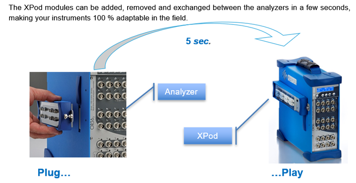
The XPod is a device that can be fixed on OR3X TW analyzer. Each XPod is associated to a block of 8 inputs.
In the connected mode, when an XPod is present each corresponding input can be routed to:
· The BNC input (Standard)
· The XPod connector
Tutorial
- First connect Xpod to the analyzer and connect your temperature probes.
- Start Analyzer
- Start NVGate
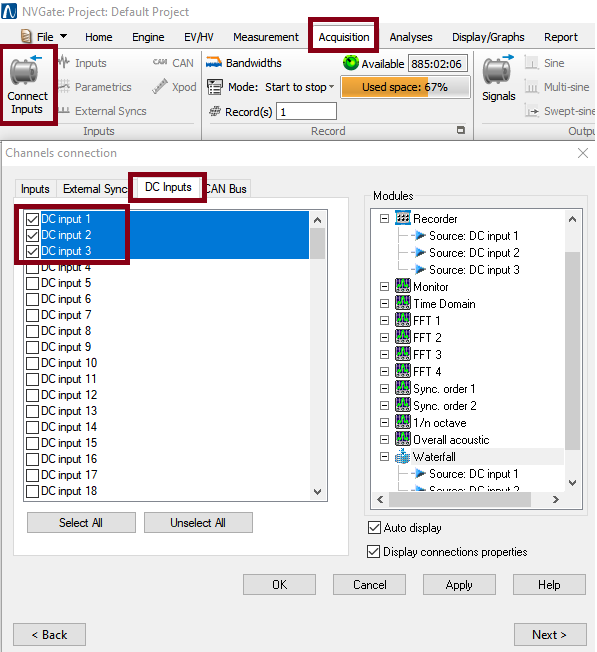
- Select a DC Input and put in in a "plug in" (recorder, waterfall (for profile)...)
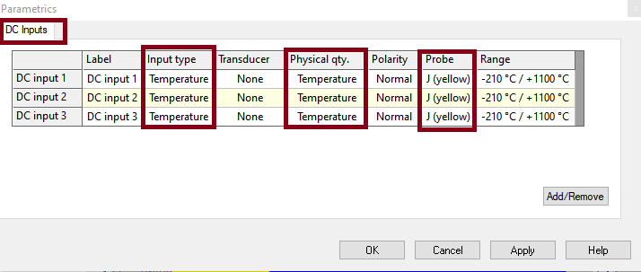
- On settings, put:
- "input type" : temperature
- "physical qty": temperature,the type of
- probe: type of probe that you are using. (range will be automatically set.)
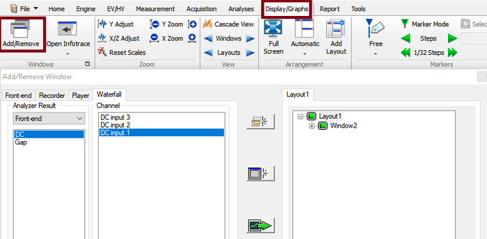
- click on add/remove windows to deal about the display
Settings
General Xpod settings
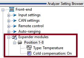
- Type: For acquisition setup preparation, the XPod presence can be simulated in the office mode:
One XPod type selector is available for each XPod position.
- Cold Compensation: Enable or disable the internal cold junction compensation for the corresponding active Temperature Xpod. This setting enables the compensation of the connectors metal junction thermocouple voltage at the Xpod side. It uses the Xpod internal temperature measurement (2 locations/Xpod) to correct the measured temperatures.
Input settings
- Input type : define the X-Pod
- Probe: Define the type of temperature probe connected on the XPod:
- Thermocouple : J, K, T, N, E
- RTD: PT100, PT1000, PT100 3 wires
For each type of probe the Temperature range is shown in the “Range” setting.
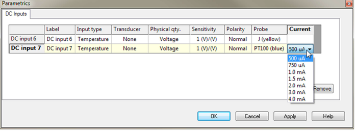
While using RTDs (PT100 PT1000), the applied current can be selected
(the standard is 500 uA)
Sensor Connector
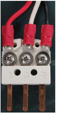
This is a standard connection. If you buy a temperature sensor it is already a cable like this :
note : for a 2 wire probe the third pin is optional. It is working with a 2 pin connector.
ABB PT 100 sensors
Some PT100 sensors have "A B B" indicator and not Gnd, - , + . In this case you need to cable the PT100 like this:
"-" is the "black" cable, the current source. It is the biggest pin.
+: is the "white cable" is the point than we measure on the midle pin.
Gnd :(A: red color) is the ground pin.
X pod is measuring beetween "+" and "gnd"

