|
|
| (9 intermediate revisions by 2 users not shown) |
| Line 1: |
Line 1: |
| | {{#seo: |
| | |title=SRS Tool: Shock Response Spectrum Analysis for OROS NVGate |
| | |keywords=SRS Tool, Shock Response Spectrum, SRS analysis, MIL-STD-810H, ECSS, NASA-STD, Smallwood filter, vibration analysis, NVGate, OROS software |
| | |description=Professional SRS analysis software for OROS NVGate. Fast shock response spectrum computation, built-in normative limit curves (MIL-STD-810H, ECSS), and automated pass/fail reporting. |
| | }} |
|
| |
|
| '''SRS Tool''' is a professional [[Shock Response Spectrum]] (SRS) analysis application built for structural dynamics engineers working with OROS [[NVGate]] data acquisition systems. It reads shock recordings directly from NVGate measurement folders, computes SRS using the [[Smallwood (1981)]] recursive digital filter, and pushes results back into NVGate as live TCP result channels — all from a single application. | | '''SRS Tool''' is a professional [https://en.wikipedia.org/wiki/Shock_response_spectrum Shock Response Spectrum] (SRS) analysis application built for structural dynamics engineers working with OROS [[NVGate]] data acquisition systems. It reads shock recordings directly from NVGate measurement folders, computes SRS using the Smallwood (1981) recursive digital filter, and pushes results back into NVGate as live TCP result channels — all from a single application. |
|
| |
|
| [[File:11_main_full.png|center|800px|thumb|'''Figure 1 — SRS Tool main window.''' Time signal with auto-detected shock zone (top right, yellow markers) and log-log SRS plot (bottom right). Three-channel triaxial measurement loaded: channels x, y, z.]] | | [[File:11_main_full.png|center|800px|thumb|'''Figure 1 — SRS Tool main window.''' Time signal with auto-detected shock zone (top right, yellow markers) and log-log SRS plot (bottom right). Three-channel triaxial measurement loaded: channels x, y, z.]] |
| Line 81: |
Line 86: |
|
| |
|
| = Installation = | | = Installation = |
| | ---- |
| | [https://partnerzone.digigram.com/s/ENrEdEMctNALAxD SRS V1.3 here ] |
| | Extract and launch the SRS_Tool.exe |
|
| |
|
| <div style="border-left:4px solid #f59f00; background:#fffbf0; padding:9px 14px; margin:10px 0; font-size:12px; border-radius:0 3px 3px 0;">
| |
| '''Note:''' NVGate does not need to be running to load signals or compute SRS. It is only required for '''Inject into NVGate'''.
| |
| </div>
| |
|
| |
|
| ----
| | ( You need to select the '''folder''' of the signal measurement. ) |
|
| |
|
| = Main Tab = | | = Main Tab = |
| Line 576: |
Line 581: |
| ---- | | ---- |
|
| |
|
|
| |
| == Confidence level indicators ==
| |
|
| |
| {| class="wikitable" style="width:100%"
| |
| ! Tag !! Meaning !! What to expect
| |
| |-
| |
| | style="background:#e8f5e9; color:#1b5e20; font-weight:bold; text-align:center;" | [normative]
| |
| | Curve taken '''directly from the published standard''' as an SRS specification.
| |
| | Breakpoints are faithful to the document. Use for compliance testing.
| |
| |-
| |
| | style="background:#fff3e0; color:#e65100; font-weight:bold; text-align:center;" | [approximate]
| |
| | Standard defines a '''time-domain waveform''' (half-sine, sawtooth…), '''not''' an SRS.
| |
| | The SRS envelope is computed from the pulse shape. For exact results, import the waveform and run compute_srs() on it.
| |
| |-
| |
| | style="background:#fce4ec; color:#880e4f; font-weight:bold; text-align:center;" | [indicative]
| |
| | Levels depend on '''mounting position, equipment mass or mission profile''', or the exact document version was not available.
| |
| | Use as a first-pass estimate only. Always verify with the applicable programme document.
| |
| |}
| |
|
| |
| All curves use '''Q = 10''' (damping ζ = 5 %) and acceleration units (g).
| |
| Between breakpoints, interpolation is '''log-log linear''' (constant dB/octave slope).
| |
|
| |
| ----
| |
|
| |
| == Space / Launcher ==
| |
|
| |
| === NASA GEVS — Protoflight, 2500 g (GSFC-STD-7000B) ===
| |
| {| class="wikitable"
| |
| ! Field !! Value
| |
| |-
| |
| | '''Tag''' || style="background:#e8f5e9; color:#1b5e20;" | [normative]
| |
| |-
| |
| | '''Reference''' || NASA GSFC-STD-7000B Rev B (2013)
| |
| |-
| |
| | '''Application''' || Hardware mounted on primary structure
| |
| |}
| |
|
| |
| '''Description:''' Protoflight SRS for hardware mounted on primary structure. The curve rises at +9 dB/oct from 20 Hz, reaching a flat plateau of 2 500 g above 100 Hz. Breakpoints are faithful to the published standard.
| |
|
| |
| {| class="wikitable" style="text-align:center;"
| |
| ! Frequency (Hz) !! Level (g)
| |
| |-
| |
| | 20 || 224
| |
| |-
| |
| | 100 || 2 500
| |
| |-
| |
| | 10 000 || 2 500
| |
| |}
| |
|
| |
| ----
| |
|
| |
| === NASA GEVS — Protoflight, 1 000 g (GSFC-STD-7000B) ===
| |
| {| class="wikitable"
| |
| ! Field !! Value
| |
| |-
| |
| | '''Tag''' || style="background:#e8f5e9; color:#1b5e20;" | [normative]
| |
| |-
| |
| | '''Reference''' || NASA GSFC-STD-7000B Rev B (2013)
| |
| |-
| |
| | '''Application''' || Hardware mounted on a panel or bracket
| |
| |}
| |
|
| |
| '''Description:''' Lower protoflight level for panel- or bracket-mounted hardware. Same +9 dB/oct slope, plateau at 1 000 g. Choose between 2 500 g and 1 000 g based on the mounting position specified in the programme's MTP/ATP.
| |
|
| |
| {| class="wikitable" style="text-align:center;"
| |
| ! Frequency (Hz) !! Level (g)
| |
| |-
| |
| | 20 || 89
| |
| |-
| |
| | 100 || 1 000
| |
| |-
| |
| | 10 000 || 1 000
| |
| |}
| |
|
| |
| ----
| |
|
| |
| === NASA GEVS — Qualification, 3 750 g (GSFC-STD-7000B) ===
| |
| {| class="wikitable"
| |
| ! Field !! Value
| |
| |-
| |
| | '''Tag''' || style="background:#e8f5e9; color:#1b5e20;" | [normative]
| |
| |-
| |
| | '''Reference''' || NASA GSFC-STD-7000B Rev B (2013)
| |
| |-
| |
| | '''Application''' || Qualification test (1.5 × protoflight 2 500 g level)
| |
| |}
| |
|
| |
| '''Description:''' Qualification SRS = 1.5 × protoflight 2 500 g level, per GSFC-STD-7000B. Applied when a dedicated qualification unit is available (as opposed to protoflight testing, which tests the flight unit at a lower margin).
| |
|
| |
| {| class="wikitable" style="text-align:center;"
| |
| ! Frequency (Hz) !! Level (g)
| |
| |-
| |
| | 20 || 335
| |
| |-
| |
| | 100 || 3 750
| |
| |-
| |
| | 10 000 || 3 750
| |
| |}
| |
|
| |
| ----
| |
|
| |
| === Ariane 5 — Equipment Bay, Component Level ===
| |
| {| class="wikitable"
| |
| ! Field !! Value
| |
| |-
| |
| | '''Tag''' || style="background:#fce4ec; color:#880e4f;" | [indicative]
| |
| |-
| |
| | '''Reference''' || Ariane 5 User's Manual Issue 5 Rev 2 (2016), Annex 2
| |
| |-
| |
| | '''Application''' || Satellite equipment bay, component level
| |
| |}
| |
|
| |
| '''Description:''' Representative SRS at the equipment bay for Ariane 5 missions. Covers separation events (SYLDA, VEB, fairing jettison, etc.). Actual levels depend on satellite integration position — contact Arianespace for flight-specific requirements.
| |
|
| |
| {| class="wikitable" style="text-align:center;"
| |
| ! Frequency (Hz) !! Level (g)
| |
| |-
| |
| | 100 || 100
| |
| |-
| |
| | 2 000 || 2 000
| |
| |-
| |
| | 10 000 || 2 000
| |
| |}
| |
|
| |
| ----
| |
|
| |
| === Ariane 6 — Component Level ===
| |
| {| class="wikitable"
| |
| ! Field !! Value
| |
| |-
| |
| | '''Tag''' || style="background:#fce4ec; color:#880e4f;" | [indicative]
| |
| |-
| |
| | '''Reference''' || Ariane 6 User's Manual Issue 1 Rev 0 (2020)
| |
| |-
| |
| | '''Application''' || Component level, all payload positions
| |
| |}
| |
|
| |
| '''Description:''' Component-level SRS for Ariane 6 missions. Slightly lower than Ariane 5 thanks to the improved fairing and dispenser design. Contact Arianespace for actual flight requirements.
| |
|
| |
| {| class="wikitable" style="text-align:center;"
| |
| ! Frequency (Hz) !! Level (g)
| |
| |-
| |
| | 100 || 80
| |
| |-
| |
| | 2 000 || 1 600
| |
| |-
| |
| | 10 000 || 1 600
| |
| |}
| |
|
| |
| ----
| |
|
| |
| === VEGA-C — Component Level ===
| |
| {| class="wikitable"
| |
| ! Field !! Value
| |
| |-
| |
| | '''Tag''' || style="background:#fce4ec; color:#880e4f;" | [indicative]
| |
| |-
| |
| | '''Reference''' || VEGA-C User's Manual Issue 0 Rev 1 (2022)
| |
| |-
| |
| | '''Application''' || Small satellite missions, component level
| |
| |}
| |
|
| |
| '''Description:''' Component-level SRS for VEGA-C missions. Contact Avio / ESA for actual flight requirements.
| |
|
| |
| {| class="wikitable" style="text-align:center;"
| |
| ! Frequency (Hz) !! Level (g)
| |
| |-
| |
| | 100 || 60
| |
| |-
| |
| | 2 000 || 1 200
| |
| |-
| |
| | 10 000 || 1 200
| |
| |}
| |
|
| |
| ----
| |
|
| |
| === ECSS-E-ST-10-03C — Protoqualification (représentatif) ===
| |
| {| class="wikitable"
| |
| ! Field !! Value
| |
| |-
| |
| | '''Tag''' || style="background:#fce4ec; color:#880e4f;" | [indicative]
| |
| |-
| |
| | '''Reference''' || ECSS-E-ST-10-03C (2012)
| |
| |-
| |
| | '''Application''' || European space programmes, proto-qualification
| |
| |}
| |
|
| |
| '''Description:''' Representative proto-qualification SRS for European space programmes. ECSS-E-ST-10-03C defines the methodology and test flow, not a universal level. Actual levels must come from the programme's System Verification Plan (SVP).
| |
|
| |
| {| class="wikitable" style="text-align:center;"
| |
| ! Frequency (Hz) !! Level (g)
| |
| |-
| |
| | 20 || 50
| |
| |-
| |
| | 100 || 500
| |
| |-
| |
| | 2 000 || 2 000
| |
| |-
| |
| | 10 000 || 2 000
| |
| |}
| |
|
| |
| ----
| |
|
| |
| == Military / Pyroshock — MIL-STD-810H Method 517 ==
| |
|
| |
| Method 517 (Pyroshock) is one of the few military standards that defines SRS limits '''directly''' — all three curves below are therefore '''[normative]'''.
| |
|
| |
| === MIL-STD-810H Meth.517 — Near-field (< 0.5 m) ===
| |
| {| class="wikitable"
| |
| ! Field !! Value
| |
| |-
| |
| | '''Tag''' || style="background:#e8f5e9; color:#1b5e20;" | [normative]
| |
| |-
| |
| | '''Reference''' || MIL-STD-810H, Method 517.2, Table 517.2-IV
| |
| |-
| |
| | '''Application''' || Equipment < 0.5 m from the pyrotechnic source
| |
| |}
| |
|
| |
| '''Description:''' Pyroshock near-field SRS. Rises at +9 dB/oct from 100 Hz, reaching a flat plateau of 10 000 g above 3 000 Hz. This is the most severe of the three field classifications.
| |
|
| |
| {| class="wikitable" style="text-align:center;"
| |
| ! Frequency (Hz) !! Level (g)
| |
| |-
| |
| | 100 || 61
| |
| |-
| |
| | 3 000 || 10 000
| |
| |-
| |
| | 10 000 || 10 000
| |
| |}
| |
|
| |
| ----
| |
|
| |
| === MIL-STD-810H Meth.517 — Mid-field (0.5–1.5 m) ===
| |
| {| class="wikitable"
| |
| ! Field !! Value
| |
| |-
| |
| | '''Tag''' || style="background:#e8f5e9; color:#1b5e20;" | [normative]
| |
| |-
| |
| | '''Reference''' || MIL-STD-810H, Method 517.2, Table 517.2-IV
| |
| |-
| |
| | '''Application''' || Equipment 0.5–1.5 m from the pyrotechnic source
| |
| |}
| |
|
| |
| '''Description:''' Pyroshock mid-field SRS. Same +9 dB/oct slope, plateau at 1 000 g above 3 000 Hz. 10× lower than near-field (20 dB).
| |
|
| |
| {| class="wikitable" style="text-align:center;"
| |
| ! Frequency (Hz) !! Level (g)
| |
| |-
| |
| | 100 || 6
| |
| |-
| |
| | 3 000 || 1 000
| |
| |-
| |
| | 10 000 || 1 000
| |
| |}
| |
|
| |
| ----
| |
|
| |
| === MIL-STD-810H Meth.517 — Far-field (> 1.5 m) ===
| |
| {| class="wikitable"
| |
| ! Field !! Value
| |
| |-
| |
| | '''Tag''' || style="background:#e8f5e9; color:#1b5e20;" | [normative]
| |
| |-
| |
| | '''Reference''' || MIL-STD-810H, Method 517.2, Table 517.2-IV
| |
| |-
| |
| | '''Application''' || Equipment > 1.5 m from the pyrotechnic source
| |
| |}
| |
|
| |
| '''Description:''' Pyroshock far-field SRS. Plateau at 100 g above 3 000 Hz. 100× lower than near-field (40 dB).
| |
|
| |
| {| class="wikitable" style="text-align:center;"
| |
| ! Frequency (Hz) !! Level (g)
| |
| |-
| |
| | 100 || 0.6
| |
| |-
| |
| | 3 000 || 100
| |
| |-
| |
| | 10 000 || 100
| |
| |}
| |
|
| |
| ----
| |
|
| |
| == Military / Mechanical Shock — MIL-STD-810H Method 516 ==
| |
|
| |
| Method 516 defines '''time-domain waveforms''' (half-sine, sawtooth), not SRS limits directly. The SRS envelopes below are computed from those pulses and are therefore '''[approximate]'''. For exact compliance, import the waveform into the SRS Tool and compute the SRS directly.
| |
|
| |
| === MIL-STD-810H Meth.516.8 — Functional, 40 g half-sine ===
| |
| {| class="wikitable"
| |
| ! Field !! Value
| |
| |-
| |
| | '''Tag''' || style="background:#fff3e0; color:#e65100;" | [approximate]
| |
| |-
| |
| | '''Reference''' || MIL-STD-810H, Method 516.8, Procedure I
| |
| |-
| |
| | '''Waveform''' || 40 g / 11 ms half-sine
| |
| |}
| |
|
| |
| '''Description:''' Functional shock — equipment must operate normally before and after. The standard defines a 40 g, 11 ms half-sine pulse. The SRS envelope peaks near 1/(2τ) ≈ 45 Hz at 2×A = 80 g and flattens to the peak amplitude above.
| |
|
| |
| {| class="wikitable" style="text-align:center;"
| |
| ! Frequency (Hz) !! Level (g)
| |
| |-
| |
| | 5 || 80
| |
| |-
| |
| | 45 || 80
| |
| |-
| |
| | 200 || 40
| |
| |-
| |
| | 2 000 || 40
| |
| |}
| |
|
| |
| ----
| |
|
| |
| === MIL-STD-810H Meth.516.8 — Crash Hazard, 40 g sawtooth ===
| |
| {| class="wikitable"
| |
| ! Field !! Value
| |
| |-
| |
| | '''Tag''' || style="background:#fff3e0; color:#e65100;" | [approximate]
| |
| |-
| |
| | '''Reference''' || MIL-STD-810H, Method 516.8, Procedure V
| |
| |-
| |
| | '''Waveform''' || 40 g / 11 ms terminal sawtooth
| |
| |}
| |
|
| |
| '''Description:''' Crash hazard — equipment must not become a hazard during a crash. The terminal sawtooth waveform has a broader SRS plateau than a half-sine of the same amplitude.
| |
|
| |
| {| class="wikitable" style="text-align:center;"
| |
| ! Frequency (Hz) !! Level (g)
| |
| |-
| |
| | 5 || 60
| |
| |-
| |
| | 100 || 60
| |
| |-
| |
| | 500 || 40
| |
| |-
| |
| | 2 000 || 40
| |
| |}
| |
|
| |
| ----
| |
|
| |
| === MIL-STD-810H Meth.516.8 — Bench Handling, 15 g half-sine ===
| |
| {| class="wikitable"
| |
| ! Field !! Value
| |
| |-
| |
| | '''Tag''' || style="background:#fff3e0; color:#e65100;" | [approximate]
| |
| |-
| |
| | '''Reference''' || MIL-STD-810H, Method 516.8, Procedure VI
| |
| |-
| |
| | '''Waveform''' || 15 g / 11 ms half-sine
| |
| |}
| |
|
| |
| '''Description:''' Bench handling — simulates drops and knocks during handling and maintenance. Lower level than functional shock.
| |
|
| |
| {| class="wikitable" style="text-align:center;"
| |
| ! Frequency (Hz) !! Level (g)
| |
| |-
| |
| | 5 || 30
| |
| |-
| |
| | 45 || 30
| |
| |-
| |
| | 200 || 15
| |
| |-
| |
| | 2 000 || 15
| |
| |}
| |
|
| |
| ----
| |
|
| |
| == Military / Naval — MIL-S-901D ==
| |
|
| |
| MIL-S-901D specifies a physical '''machine test''' (Lightweight Shock Machine or floating barge), not an SRS limit. The curves below are '''[indicative]''' envelopes representative of the machine output.
| |
|
| |
| === MIL-S-901D — Grade A (lightweight, < 136 kg) ===
| |
| {| class="wikitable"
| |
| ! Field !! Value
| |
| |-
| |
| | '''Tag''' || style="background:#fce4ec; color:#880e4f;" | [indicative]
| |
| |-
| |
| | '''Reference''' || MIL-S-901D (1989), Grade A
| |
| |-
| |
| | '''Application''' || US Navy — lightweight equipment (< 136 kg)
| |
| |}
| |
|
| |
| '''Description:''' High-energy naval shock test for lightweight equipment. Uses the Lightweight Shock Machine (LWSM). Representative SRS envelope of the machine output.
| |
|
| |
| {| class="wikitable" style="text-align:center;"
| |
| ! Frequency (Hz) !! Level (g)
| |
| |-
| |
| | 20 || 100
| |
| |-
| |
| | 100 || 500
| |
| |-
| |
| | 2 000 || 2 000
| |
| |-
| |
| | 10 000 || 2 000
| |
| |}
| |
|
| |
| ----
| |
|
| |
| === MIL-S-901D — Grade B (mediumweight, 136–2 268 kg) ===
| |
| {| class="wikitable"
| |
| ! Field !! Value
| |
| |-
| |
| | '''Tag''' || style="background:#fce4ec; color:#880e4f;" | [indicative]
| |
| |-
| |
| | '''Reference''' || MIL-S-901D (1989), Grade B
| |
| |-
| |
| | '''Application''' || US Navy — medium-weight equipment (136–2 268 kg)
| |
| |}
| |
|
| |
| '''Description:''' Naval shock using the floating barge platform. Lower levels than Grade A due to the larger test article mass and different test rig.
| |
|
| |
| {| class="wikitable" style="text-align:center;"
| |
| ! Frequency (Hz) !! Level (g)
| |
| |-
| |
| | 20 || 50
| |
| |-
| |
| | 100 || 250
| |
| |-
| |
| | 2 000 || 1 000
| |
| |-
| |
| | 10 000 || 1 000
| |
| |}
| |
|
| |
| ----
| |
|
| |
| == Aviation — RTCA DO-160G Section 7 ==
| |
|
| |
| DO-160G Section 7 defines '''time-domain shock pulses''', not SRS limits. All three curves are '''[approximate]''' envelopes computed from those pulses.
| |
|
| |
| === DO-160G Sect.7 — Cat. B, Operational (6 g half-sine) ===
| |
| {| class="wikitable"
| |
| ! Field !! Value
| |
| |-
| |
| | '''Tag''' || style="background:#fff3e0; color:#e65100;" | [approximate]
| |
| |-
| |
| | '''Reference''' || RTCA DO-160G, Section 7, Category B
| |
| |-
| |
| | '''Waveform''' || 6 g / 11 ms half-sine
| |
| |}
| |
|
| |
| '''Description:''' Aircraft operational shock — in-service turbulence, hard landings, taxiing. The least severe DO-160G shock category.
| |
|
| |
| {| class="wikitable" style="text-align:center;"
| |
| ! Frequency (Hz) !! Level (g)
| |
| |-
| |
| | 5 || 12
| |
| |-
| |
| | 45 || 12
| |
| |-
| |
| | 200 || 6
| |
| |-
| |
| | 2 000 || 6
| |
| |}
| |
|
| |
| ----
| |
|
| |
| === DO-160G Sect.7 — Cat. C, Bench Handling (15 g half-sine) ===
| |
| {| class="wikitable"
| |
| ! Field !! Value
| |
| |-
| |
| | '''Tag''' || style="background:#fff3e0; color:#e65100;" | [approximate]
| |
| |-
| |
| | '''Reference''' || RTCA DO-160G, Section 7, Category C
| |
| |-
| |
| | '''Waveform''' || 15 g / 11 ms half-sine
| |
| |}
| |
|
| |
| '''Description:''' Bench handling shock for avionics — drops, knocks during maintenance. Matches MIL-STD-810H Procedure VI levels.
| |
|
| |
| {| class="wikitable" style="text-align:center;"
| |
| ! Frequency (Hz) !! Level (g)
| |
| |-
| |
| | 5 || 30
| |
| |-
| |
| | 45 || 30
| |
| |-
| |
| | 200 || 15
| |
| |-
| |
| | 2 000 || 15
| |
| |}
| |
|
| |
| ----
| |
|
| |
| === DO-160G Sect.7 — Cat. D, Crash (20 g) ===
| |
| {| class="wikitable"
| |
| ! Field !! Value
| |
| |-
| |
| | '''Tag''' || style="background:#fff3e0; color:#e65100;" | [approximate]
| |
| |-
| |
| | '''Reference''' || RTCA DO-160G, Section 7, Category D
| |
| |-
| |
| | '''Waveform''' || 20 g equivalent crash pulse
| |
| |}
| |
|
| |
| '''Description:''' Crash / emergency landing survivability requirement. Equipment must not create a hazard to occupants during a crash sequence.
| |
|
| |
| {| class="wikitable" style="text-align:center;"
| |
| ! Frequency (Hz) !! Level (g)
| |
| |-
| |
| | 5 || 40
| |
| |-
| |
| | 45 || 40
| |
| |-
| |
| | 200 || 20
| |
| |-
| |
| | 2 000 || 20
| |
| |}
| |
|
| |
| ----
| |
|
| |
| == European Defence ==
| |
|
| |
| === DEF STAN 00-35 Pt.3 — Category M (Mechanical) ===
| |
| {| class="wikitable"
| |
| ! Field !! Value
| |
| |-
| |
| | '''Tag''' || style="background:#fce4ec; color:#880e4f;" | [indicative]
| |
| |-
| |
| | '''Reference''' || DEF STAN 00-35 Part 3 Issue 4, Category M
| |
| |-
| |
| | '''Application''' || UK defence — general mechanical shock
| |
| |}
| |
|
| |
| '''Description:''' UK Ministry of Defence standard for general mechanical shock environments. Levels depend on the platform category. Always verify against the Test Schedule (TS) applicable to the programme.
| |
|
| |
| {| class="wikitable" style="text-align:center;"
| |
| ! Frequency (Hz) !! Level (g)
| |
| |-
| |
| | 10 || 25
| |
| |-
| |
| | 100 || 250
| |
| |-
| |
| | 2 000 || 1 000
| |
| |-
| |
| | 10 000 || 1 000
| |
| |}
| |
|
| |
| ----
| |
|
| |
| === DEF STAN 00-35 Pt.3 — Category P (Pyrotechnic) ===
| |
| {| class="wikitable"
| |
| ! Field !! Value
| |
| |-
| |
| | '''Tag''' || style="background:#fce4ec; color:#880e4f;" | [indicative]
| |
| |-
| |
| | '''Reference''' || DEF STAN 00-35 Part 3 Issue 4, Category P
| |
| |-
| |
| | '''Application''' || UK defence — aircraft store separation (pyrotechnic)
| |
| |}
| |
|
| |
| '''Description:''' Pyrotechnic shock for aircraft-delivered stores (bombs, missiles). More severe than Category M. Verify against the applicable Test Schedule.
| |
|
| |
| {| class="wikitable" style="text-align:center;"
| |
| ! Frequency (Hz) !! Level (g)
| |
| |-
| |
| | 100 || 100
| |
| |-
| |
| | 1 000 || 2 000
| |
| |-
| |
| | 10 000 || 2 000
| |
| |}
| |
|
| |
| ----
| |
|
| |
| === GAM EG-13 — Choc sévère (pyrotechnique) ===
| |
| {| class="wikitable"
| |
| ! Field !! Value
| |
| |-
| |
| | '''Tag''' || style="background:#fce4ec; color:#880e4f;" | [indicative]
| |
| |-
| |
| | '''Reference''' || DGA GAM EG-13 (2002), Tableau 3, Choc sévère
| |
| |-
| |
| | '''Application''' || French DGA — severe pyrotechnic shock environment
| |
| |}
| |
|
| |
| '''Description:''' French DGA (Direction Générale de l'Armement) standard for severe shock, typically from pyrotechnic devices (ejection seats, weapon release). Verify exact levels in Table 3 of the applicable programme document.
| |
|
| |
| {| class="wikitable" style="text-align:center;"
| |
| ! Frequency (Hz) !! Level (g)
| |
| |-
| |
| | 20 || 40
| |
| |-
| |
| | 100 || 200
| |
| |-
| |
| | 1 000 || 2 000
| |
| |-
| |
| | 10 000 || 2 000
| |
| |}
| |
|
| |
| ----
| |
|
| |
| === GAM EG-13 — Choc modéré (mécanique) ===
| |
| {| class="wikitable"
| |
| ! Field !! Value
| |
| |-
| |
| | '''Tag''' || style="background:#fce4ec; color:#880e4f;" | [indicative]
| |
| |-
| |
| | '''Reference''' || DGA GAM EG-13 (2002), Tableau 3, Choc modéré
| |
| |-
| |
| | '''Application''' || French DGA — moderate mechanical shock environment
| |
| |}
| |
|
| |
| '''Description:''' French DGA standard for moderate mechanical shock (vehicle impacts, transport drops). Significantly lower levels than the pyrotechnic environment.
| |
|
| |
| {| class="wikitable" style="text-align:center;"
| |
| ! Frequency (Hz) !! Level (g)
| |
| |-
| |
| | 10 || 20
| |
| |-
| |
| | 100 || 100
| |
| |-
| |
| | 1 000 || 500
| |
| |-
| |
| | 5 000 || 500
| |
| |}
| |
|
| |
| ----
| |
|
| |
| == NATO — STANAG 4370 / AECTP 201 ==
| |
|
| |
| === STANAG 4370 AECTP 201 — Meth.417 Pyroshock ===
| |
| {| class="wikitable"
| |
| ! Field !! Value
| |
| |-
| |
| | '''Tag''' || style="background:#fce4ec; color:#880e4f;" | [indicative]
| |
| |-
| |
| | '''Reference''' || STANAG 4370 AECTP 201, Method 417 (Ed.3, 2009)
| |
| |-
| |
| | '''Application''' || NATO — pyroshock, severity level 3 (severe platform)
| |
| |}
| |
|
| |
| '''Description:''' NATO standardised pyroshock test method (SRS method). The curve shown is representative of severity level 3 (severe platform shock). Actual levels must be drawn from the applicable NATO programme documents.
| |
|
| |
| {| class="wikitable" style="text-align:center;"
| |
| ! Frequency (Hz) !! Level (g)
| |
| |-
| |
| | 100 || 50
| |
| |-
| |
| | 1 000 || 2 000
| |
| |-
| |
| | 10 000 || 2 000
| |
| |}
| |
|
| |
| ----
| |
|
| |
| === STANAG 4370 AECTP 201 — Meth.403 Mechanical Shock ===
| |
| {| class="wikitable"
| |
| ! Field !! Value
| |
| |-
| |
| | '''Tag''' || style="background:#fff3e0; color:#e65100;" | [approximate]
| |
| |-
| |
| | '''Reference''' || STANAG 4370 AECTP 201, Method 403 (Ed.3, 2009)
| |
| |-
| |
| | '''Waveform''' || Half-sine pulse, severity level 3
| |
| |}
| |
|
| |
| '''Description:''' NATO mechanical shock — Method 403 defines time-domain pulses (half-sine), not SRS directly. The curve shown is an SRS envelope computed from the severity level 3 half-sine waveform.
| |
|
| |
| {| class="wikitable" style="text-align:center;"
| |
| ! Frequency (Hz) !! Level (g)
| |
| |-
| |
| | 5 || 50
| |
| |-
| |
| | 50 || 50
| |
| |-
| |
| | 500 || 25
| |
| |-
| |
| | 2 000 || 25
| |
| |}
| |
|
| |
| ----
| |
|
| |
| == Industrial — IEC 60068-2-27 ==
| |
|
| |
| IEC 60068-2-27 (Test Ea) defines '''half-sine time-domain pulses''', not SRS limits. All curves are '''[approximate]'''.
| |
|
| |
| === IEC 60068-2-27 — Test Ea, 15 g / 11 ms half-sine ===
| |
| {| class="wikitable"
| |
| ! Field !! Value
| |
| |-
| |
| | '''Tag''' || style="background:#fff3e0; color:#e65100;" | [approximate]
| |
| |-
| |
| | '''Reference''' || IEC 60068-2-27 Ed.3 (2008), Test Ea — 15 g / 11 ms
| |
| |-
| |
| | '''Application''' || General industrial equipment — standard shock level
| |
| |}
| |
|
| |
| '''Description:''' Standard environmental test shock (Test Ea). Widely used for industrial and commercial equipment qualification. 15 g / 11 ms half-sine is the most common combination.
| |
|
| |
| {| class="wikitable" style="text-align:center;"
| |
| ! Frequency (Hz) !! Level (g)
| |
| |-
| |
| | 5 || 30
| |
| |-
| |
| | 45 || 30
| |
| |-
| |
| | 200 || 15
| |
| |-
| |
| | 2 000 || 15
| |
| |}
| |
|
| |
| ----
| |
|
| |
| === IEC 60068-2-27 — Test Ea, 50 g / 11 ms half-sine ===
| |
| {| class="wikitable"
| |
| ! Field !! Value
| |
| |-
| |
| | '''Tag''' || style="background:#fff3e0; color:#e65100;" | [approximate]
| |
| |-
| |
| | '''Reference''' || IEC 60068-2-27 Ed.3 (2008), Test Ea — 50 g / 11 ms (severe)
| |
| |-
| |
| | '''Application''' || Industrial equipment — severe shock level
| |
| |}
| |
|
| |
| '''Description:''' Severe industrial shock. Used for rugged equipment or harsh installation environments.
| |
|
| |
| {| class="wikitable" style="text-align:center;"
| |
| ! Frequency (Hz) !! Level (g)
| |
| |-
| |
| | 5 || 100
| |
| |-
| |
| | 45 || 100
| |
| |-
| |
| | 200 || 50
| |
| |-
| |
| | 2 000 || 50
| |
| |}
| |
|
| |
| ----
| |
|
| |
| === IEC 60068-2-27 — Test Ea, 100 g / 6 ms half-sine ===
| |
| {| class="wikitable"
| |
| ! Field !! Value
| |
| |-
| |
| | '''Tag''' || style="background:#fff3e0; color:#e65100;" | [approximate]
| |
| |-
| |
| | '''Reference''' || IEC 60068-2-27 Ed.3 (2008), Test Ea — 100 g / 6 ms
| |
| |-
| |
| | '''Application''' || Industrial equipment — harsh shock level
| |
| |}
| |
|
| |
| '''Description:''' Harsh shock level — short duration (6 ms) shifts the SRS peak to ~83 Hz. Used for equipment exposed to impacts, sudden accelerations, or harsh transport.
| |
|
| |
| {| class="wikitable" style="text-align:center;"
| |
| ! Frequency (Hz) !! Level (g)
| |
| |-
| |
| | 5 || 200
| |
| |-
| |
| | 83 || 200
| |
| |-
| |
| | 500 || 100
| |
| |-
| |
| | 2 000 || 100
| |
| |}
| |
|
| |
| ----
| |
|
| |
| == Railway — IEC 61373 ==
| |
|
| |
| IEC 61373 defines '''time-domain shock pulses''' for railway equipment. All curves are '''[approximate]'''.
| |
|
| |
| === IEC 61373 Cat.1 Class B — Railway, Vehicle Body ===
| |
| {| class="wikitable"
| |
| ! Field !! Value
| |
| |-
| |
| | '''Tag''' || style="background:#fff3e0; color:#e65100;" | [approximate]
| |
| |-
| |
| | '''Reference''' || IEC 61373 Ed.2 (2010), Category 1 Class B
| |
| |-
| |
| | '''Application''' || Equipment mounted on the vehicle body (interior)
| |
| |}
| |
|
| |
| '''Description:''' Functional shock for body-mounted railway equipment. IEC 61373 defines a 3 g / 30 ms half-sine. The long duration (30 ms) places the SRS peak at only ~16 Hz — the lowest peak frequency of all curves in the library.
| |
|
| |
| {| class="wikitable" style="text-align:center;"
| |
| ! Frequency (Hz) !! Level (g)
| |
| |-
| |
| | 2 || 6
| |
| |-
| |
| | 16 || 6
| |
| |-
| |
| | 200 || 3
| |
| |-
| |
| | 2 000 || 3
| |
| |}
| |
|
| |
| ----
| |
|
| |
| === IEC 61373 Cat.1 Class A — Railway, Bogie-Mounted ===
| |
| {| class="wikitable"
| |
| ! Field !! Value
| |
| |-
| |
| | '''Tag''' || style="background:#fff3e0; color:#e65100;" | [approximate]
| |
| |-
| |
| | '''Reference''' || IEC 61373 Ed.2 (2010), Category 1 Class A
| |
| |-
| |
| | '''Application''' || Equipment mounted on the bogie (running gear)
| |
| |}
| |
|
| |
| '''Description:''' Bogie-mounted equipment is directly exposed to rail irregularities and rail joints. Significantly higher levels than Class B (vehicle body). IEC 61373 defines a time-domain pulse, not an SRS.
| |
|
| |
| {| class="wikitable" style="text-align:center;"
| |
| ! Frequency (Hz) !! Level (g)
| |
| |-
| |
| | 2 || 15
| |
| |-
| |
| | 16 || 15
| |
| |-
| |
| | 200 || 8
| |
| |-
| |
| | 2 000 || 8
| |
| |}
| |
|
| |
| ----
| |
|
| |
| === IEC 61373 Cat.2 — Railway, Under-Body Mounted ===
| |
| {| class="wikitable"
| |
| ! Field !! Value
| |
| |-
| |
| | '''Tag''' || style="background:#fff3e0; color:#e65100;" | [approximate]
| |
| |-
| |
| | '''Reference''' || IEC 61373 Ed.2 (2010), Category 2
| |
| |-
| |
| | '''Application''' || Under-body mounted equipment, axle box area
| |
| |}
| |
|
| |
| '''Description:''' Most severe shock category in IEC 61373. Under-body equipment (including axle-box area) is exposed to the highest shock levels on a railway vehicle.
| |
|
| |
| {| class="wikitable" style="text-align:center;"
| |
| ! Frequency (Hz) !! Level (g)
| |
| |-
| |
| | 2 || 50
| |
| |-
| |
| | 16 || 50
| |
| |-
| |
| | 200 || 25
| |
| |-
| |
| | 2 000 || 25
| |
| |}
| |
|
| |
| ----
| |
|
| |
| == Summary table ==
| |
|
| |
| {| class="wikitable sortable" style="width:100%; font-size:90%;"
| |
| ! Standard !! Sector !! Tag !! Peak level !! Freq. range
| |
| |-
| |
| | NASA GEVS 2500 g || Space || style="background:#e8f5e9; color:#1b5e20;" | normative || 2 500 g || 20–10 000 Hz
| |
| |-
| |
| | NASA GEVS 1000 g || Space || style="background:#e8f5e9; color:#1b5e20;" | normative || 1 000 g || 20–10 000 Hz
| |
| |-
| |
| | NASA GEVS 3750 g (Qual.) || Space || style="background:#e8f5e9; color:#1b5e20;" | normative || 3 750 g || 20–10 000 Hz
| |
| |-
| |
| | Ariane 5 Equipment Bay || Space || style="background:#fce4ec; color:#880e4f;" | indicative || 2 000 g || 100–10 000 Hz
| |
| |-
| |
| | Ariane 6 || Space || style="background:#fce4ec; color:#880e4f;" | indicative || 1 600 g || 100–10 000 Hz
| |
| |-
| |
| | VEGA-C || Space || style="background:#fce4ec; color:#880e4f;" | indicative || 1 200 g || 100–10 000 Hz
| |
| |-
| |
| | ECSS-E-ST-10-03C Protoqual. || Space || style="background:#fce4ec; color:#880e4f;" | indicative || 2 000 g || 20–10 000 Hz
| |
| |-
| |
| | MIL-STD-810H M517 Near-field || Military / Pyro || style="background:#e8f5e9; color:#1b5e20;" | normative || 10 000 g || 100–10 000 Hz
| |
| |-
| |
| | MIL-STD-810H M517 Mid-field || Military / Pyro || style="background:#e8f5e9; color:#1b5e20;" | normative || 1 000 g || 100–10 000 Hz
| |
| |-
| |
| | MIL-STD-810H M517 Far-field || Military / Pyro || style="background:#e8f5e9; color:#1b5e20;" | normative || 100 g || 100–10 000 Hz
| |
| |-
| |
| | MIL-STD-810H M516 Functional 40 g || Military / Mech || style="background:#fff3e0; color:#e65100;" | approximate || 80 g (2×A) || 5–2 000 Hz
| |
| |-
| |
| | MIL-STD-810H M516 Crash 40 g || Military / Mech || style="background:#fff3e0; color:#e65100;" | approximate || 60 g || 5–2 000 Hz
| |
| |-
| |
| | MIL-STD-810H M516 Bench 15 g || Military / Mech || style="background:#fff3e0; color:#e65100;" | approximate || 30 g || 5–2 000 Hz
| |
| |-
| |
| | MIL-S-901D Grade A || Military / Naval || style="background:#fce4ec; color:#880e4f;" | indicative || 2 000 g || 20–10 000 Hz
| |
| |-
| |
| | MIL-S-901D Grade B || Military / Naval || style="background:#fce4ec; color:#880e4f;" | indicative || 1 000 g || 20–10 000 Hz
| |
| |-
| |
| | DO-160G Cat. B 6 g || Aviation || style="background:#fff3e0; color:#e65100;" | approximate || 12 g || 5–2 000 Hz
| |
| |-
| |
| | DO-160G Cat. C 15 g || Aviation || style="background:#fff3e0; color:#e65100;" | approximate || 30 g || 5–2 000 Hz
| |
| |-
| |
| | DO-160G Cat. D 20 g || Aviation || style="background:#fff3e0; color:#e65100;" | approximate || 40 g || 5–2 000 Hz
| |
| |-
| |
| | DEF STAN 00-35 Cat. M || European Defence || style="background:#fce4ec; color:#880e4f;" | indicative || 1 000 g || 10–10 000 Hz
| |
| |-
| |
| | DEF STAN 00-35 Cat. P || European Defence || style="background:#fce4ec; color:#880e4f;" | indicative || 2 000 g || 100–10 000 Hz
| |
| |-
| |
| | GAM EG-13 Choc sévère || European Defence (DGA) || style="background:#fce4ec; color:#880e4f;" | indicative || 2 000 g || 20–10 000 Hz
| |
| |-
| |
| | GAM EG-13 Choc modéré || European Defence (DGA) || style="background:#fce4ec; color:#880e4f;" | indicative || 500 g || 10–5 000 Hz
| |
| |-
| |
| | STANAG 4370 AECTP-201 M417 || NATO || style="background:#fce4ec; color:#880e4f;" | indicative || 2 000 g || 100–10 000 Hz
| |
| |-
| |
| | STANAG 4370 AECTP-201 M403 || NATO || style="background:#fff3e0; color:#e65100;" | approximate || 50 g || 5–2 000 Hz
| |
| |-
| |
| | IEC 60068-2-27 15 g / 11 ms || Industrial || style="background:#fff3e0; color:#e65100;" | approximate || 30 g || 5–2 000 Hz
| |
| |-
| |
| | IEC 60068-2-27 50 g / 11 ms || Industrial || style="background:#fff3e0; color:#e65100;" | approximate || 100 g || 5–2 000 Hz
| |
| |-
| |
| | IEC 60068-2-27 100 g / 6 ms || Industrial || style="background:#fff3e0; color:#e65100;" | approximate || 200 g || 5–2 000 Hz
| |
| |-
| |
| | IEC 61373 Cat.1 Class B || Railway || style="background:#fff3e0; color:#e65100;" | approximate || 6 g || 2–2 000 Hz
| |
| |-
| |
| | IEC 61373 Cat.1 Class A || Railway || style="background:#fff3e0; color:#e65100;" | approximate || 15 g || 2–2 000 Hz
| |
| |-
| |
| | IEC 61373 Cat.2 Under-body || Railway || style="background:#fff3e0; color:#e65100;" | approximate || 50 g || 2–2 000 Hz
| |
| |}
| |
|
| |
| ----
| |
|
| |
|
| == How the SRS Tool uses these curves == | | == How the SRS Tool uses these curves == |
| Line 1,491: |
Line 587: |
| # The tool interpolates the curve at the same frequency resolution as the measured SRS using log-log linear interpolation. | | # The tool interpolates the curve at the same frequency resolution as the measured SRS using log-log linear interpolation. |
| # Margin is computed point-by-point: '''Margin (dB) = 20 × log₁₀(limit / SRS)''' | | # Margin is computed point-by-point: '''Margin (dB) = 20 × log₁₀(limit / SRS)''' |
| ** Positive margin → SRS is below the limit ('''PASS''' at that frequency)
| |
| ** Negative margin → SRS exceeds the limit ('''FAIL''' at that frequency)
| |
| # The overall result is PASS only if the margin is positive at '''all''' frequencies. | | # The overall result is PASS only if the margin is positive at '''all''' frequencies. |
|
| |
|
SRS Tool is a professional Shock Response Spectrum (SRS) analysis application built for structural dynamics engineers working with OROS NVGate data acquisition systems. It reads shock recordings directly from NVGate measurement folders, computes SRS using the Smallwood (1981) recursive digital filter, and pushes results back into NVGate as live TCP result channels — all from a single application.
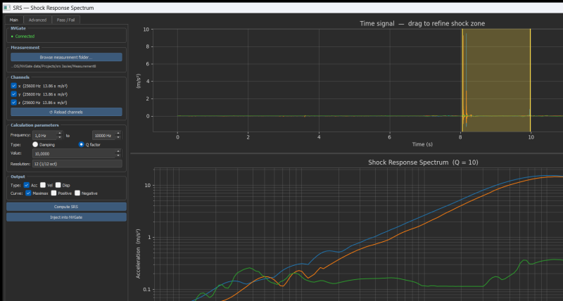
Figure 1 — SRS Tool main window. Time signal with auto-detected shock zone (top right, yellow markers) and log-log SRS plot (bottom right). Three-channel triaxial measurement loaded: channels x, y, z.
What makes SRS Tool unique
SRS Tool is built around the idea that an engineer should go from raw measurement to qualification verdict in under one minute.
| Feature
|
OROS SRS Tool
|
Typical alternatives
|
| 30+ normative limit curves built-in — MIL-STD-810H, ECSS, NASA-STD, DEF-STAN, ready to use with no setup
|
✔ Included
|
✘ Manual entry only
|
| Multi-channel Pass/Fail with per-channel verdict — x, y, z compared simultaneously in one run
|
✔ Included
|
✘ One channel at a time
|
| NVGate TCP result injection — log-log display, autoscaled, direct to project
|
✔ Native
|
✘ Not available
|
| Automatic shock zone detection — envelope algorithm, runs on load
|
✔ Automatic
|
~ Manual only
|
| Primary + Residual SRS in a single computation pass
|
✔ One click
|
~ Two separate runs
|
| SRSS + Worst-case Envelope — triaxial multi-axis combination
|
✔ Included
|
✘ Rarely available
|
| Interactive dB cursor on Pass/Fail chart — frequency, SRS, limit, margin at a glance
|
✔ Included
|
✘ Rarely available
|
Full feature list
- Signal acquisition: reads NVGate signal files directly
- Multi-channel: up to 10+ simultaneous channels; channel labels read from NVGate recording metadata (e.g. x, y, z)
- Smallwood recursive filter: vectorised NumPy implementation; all frequencies computed in a single forward pass
- Frequency axis: 1/3, 1/6, 1/12 or 1/24 octave resolution; user-defined f_min / f_max
- SRS types: Maximax (absolute maximum), Positive, Negative
- Physical quantities: Acceleration SRS + derived Pseudo-Velocity SRS + Pseudo-Displacement SRS
- Shock zone: auto-detection + manual override (drag on plot or type Start/End in seconds)
- Residual SRS: computes SRS on the signal segment after the shock ends
- Multi-axis combination: SRSS and/or Worst-case Envelope across all loaded channels
- Pass/Fail: 30+ built-in normative curves; user CSV; scale factor (dB); multi-channel worst-case
- CSV export: full table (per-channel SRS, SRSS, limit, per-channel margin, worst margin, status)
- PNG export: Pass/Fail chart at 150 dpi
- NVGate injection: injects all SRS curves into NVGate on log-log display, autoscaled
- Preprocessing: DC offset removal, noise floor suppression
- Dark theme: optimised for lab-room screen visibility
Quick Start
⚡ Five steps from measurement folder to qualification verdict
- Main tab → Select signal folder… → navigate to the NVGate Measurement folder
- Channels appear automatically — shock zone is auto-detected (yellow markers on signal plot)
- Set Q = 10, range 1–10 000 Hz, resolution 1/12 oct → click Compute SRS
- Pass / Fail tab → limit curve is pre-set to MIL-STD-810H Mid-field → click ▶ Run Pass / Fail
- Read the per-channel verdict, export CSV / PNG, or click Inject into NVGate
Installation
SRS V1.3 here
Extract and launch the SRS_Tool.exe
( You need to select the folder of the signal measurement. )
Main Tab
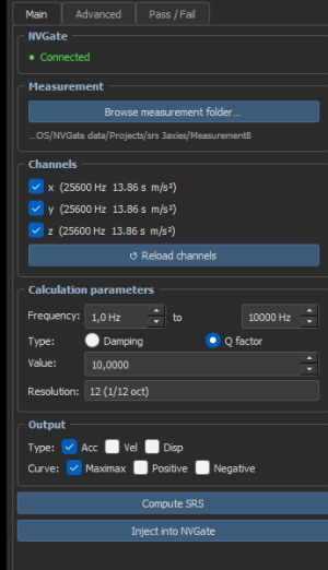
Figure 2 — Main tab controls. From top: NVGate connection indicator, Signal folder, channel checkboxes with Reload, Calculation parameters, Output type selectors, Compute and Inject buttons.
Signal
Click Select signal folder… to open a folder browser (default root: C:\OROS\NVGate data\Projects). Select the Measurement folder — channels are listed and the signal is plotted immediately.
Channels
One checkbox per recorded channel, showing label, sampling rate, duration and unit:
  ☑  x   (25 600 Hz   13.86 s   m/s²)
  ☑  y   (25 600 Hz   13.86 s   m/s²)
  ☑  z   (25 600 Hz   13.86 s   m/s²)
Channel labels (x, y, z…) come from the Name field set by the operator in NVGate at recording time.
Uncheck a channel to exclude it. ↺ Reload channels re-reads files from disk after a new recording.
Calculation parameters
| Parameter |
Description |
Recommended default
|
| Frequency range |
f_min to f_max of the SRS output |
1 Hz → 10 000 Hz
|
| Q / Damping |
Q factor or damping ratio ζ (linked: Q = 1/2ζ) |
Q = 10 (ζ = 5 %)
|
| Resolution |
Octave subdivision: 1/3, 1/6, 1/12, 1/24 oct |
1/12 octave
|
Q = 10 (ζ = 5%) is the universal standard for aerospace shock SRS — MIL-STD-810H, ECSS-E-ST-10-03C, NASA-STD-7003A all specify this value. f_max is auto-clamped to Nyquist (f_s / 2).
Output
- Type
- Acc — Acceleration SRS. Always available. Vel — Pseudo-velocity SRS. Disp — Pseudo-displacement SRS. (Vel and Disp require an acceleration input.)
- Curve
- Maximax — max(positive, |negative|). The standard curve required by most norms. Positive — max tensile response. Negative — max compressive response.
Signal and SRS plots
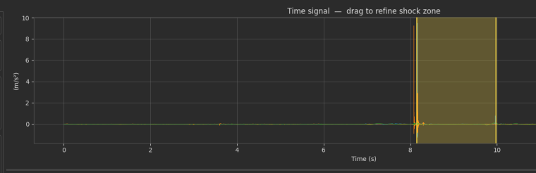
Figure 3 — Time signal plot. Three channels (x/y/z) overlaid. Yellow dashed lines mark the auto-detected shock zone. Drag horizontally anywhere on the plot to redefine the zone manually.
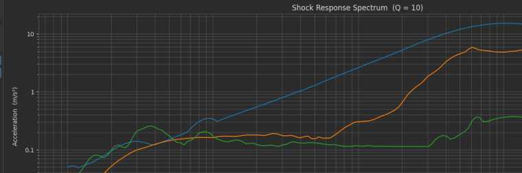
Figure 4 — SRS log-log plot. Channels x (blue), y (orange), z (green). Each curve is the Maximax acceleration SRS over the detected shock zone. Q = 10, 1/12 octave, 1–10 000 Hz.
Injecting results into NVGate
Click Inject into NVGate (or the duplicate button in the Advanced tab) to send all computed curves via the NVDrive TCP protocol as NVD REAL SPECTRUM channels:
- All SRS curves → separate TCP result channels
- X and Y axes: log scale (set automatically)
- Y axis: autoscaled
- All curves displayed in window SRS_Results of Layout1
NVGate channel naming convention:
SRS Acc Shock AbsMax: x
SRS Acc Shock AbsMax: y
SRS Acc Shock AbsMax: z
Advanced Tab
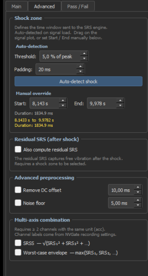
Figure 5 — Advanced tab. Shock zone section (auto-detection parameters + manual Start/End override), Residual SRS option, preprocessing, and multi-axis SRSS / Envelope.
Shock Zone
The shock zone is auto-detected every time a signal loads — you normally do not need to touch these settings. Use manual override only to fine-tune the boundary.
Auto-detection
The detection algorithm:
- Compute a smoothed envelope: rolling mean of |signal| over a 3 ms window
- Trigger threshold = Threshold % × peak envelope
- Zone = first to last sample above threshold
- Expand by Padding ms on each side, clamped to signal bounds
| Parameter |
Effect |
Default
|
| Threshold (% of peak) |
Lower → wider zone; higher → core impact only |
5 %
|
| Padding (ms) |
Symmetric margin added on both sides of detected zone |
20 ms
|
Padding example: shock detected at 8.055 s – 9.978 s with 20 ms padding → zone becomes 8.035 s – 9.998 s, ensuring ring-down is fully captured.
Manual override
Type Start and End (seconds, 3-decimal precision) — the yellow markers on the signal plot update immediately.
Dragging on the signal plot synchronises the spinboxes in return.
Residual SRS
Check Also compute residual SRS to run a second computation on the signal after the shock zone end. This captures the free-vibration decay required by MIL-STD-810H Method 517 and ECSS-E-ST-10-03C for fragility assessment. Residual curves appear on the SRS plot labelled "(residual)".
Advanced Preprocessing
| Option |
Effect |
Typical use
|
| Remove DC offset (N ms) |
Subtracts the mean of the first N ms from the whole signal |
Sensor bias, thermal drift
|
| Noise floor (N ms) |
Zeroes the first N ms |
Pre-trigger noise before impact
|
Multi-axis Combination
Enabled automatically when ≥ 2 acceleration channels are loaded. Check one or both options before computing:
| Option |
Formula |
Display
|
| SRSS — Square Root Sum of Squares |
√(SRS_x² + SRS_y² + SRS_z²) |
White dashed curve, Maximax only
|
| Worst-case Envelope |
max(SRS_x, SRS_y, SRS_z) at each frequency |
Orange dash-dot curve, all types
|
Pass / Fail Tab
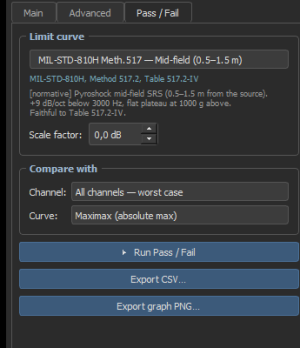
Figure 6 — Pass/Fail controls. Grouped limit curve library (30+ curves), user CSV option, scale factor, channel selector, Run button, and export buttons.
The Pass/Fail tab compares computed SRS against any normative or user-defined limit curve.
Built-in limit curve library
30+ normative curves are pre-programmed — select a standard from the grouped drop-down and run immediately. No other standalone SRS tool provides this library out of the box.
| Standard |
Curves included
|
| MIL-STD-810H — Method 517 |
Near-field (< 0.3 m), Mid-field ★ (0.5–1.5 m), Far-field (> 1.5 m), Gunfire, Tall vehicles
|
| ECSS-E-ST-10-03C |
Protoflight, Proto+, Acceptance, Qualification, Protoqualification (equipment & system level)
|
| NASA-STD-7003A |
Payload near/far-field, structure-borne near/far
|
| DEF-STAN 00-35 |
Land vehicle, Ship (deck), Airborne external/internal
|
| MIL-S-901D |
High-impact shock Grade A / Grade B
|
| IEST-RP-DTE032 |
Light / medium / heavy equipment
|
| RTCA DO-160G |
Avionics Cat. A / B / C
|
★ MIL-STD-810H Mid-field is the default — the most common qualification specification.
User-defined CSV
Select ← User-defined (CSV), load a two-column file (Hz, g). Interpolation is log-log linear between breakpoints. Example:
10, 5 100, 50 2000, 50 10000, 50
Scale factor (dB)
Scales the limit curve before comparison: L_scaled(f) = L_nominal(f) × 10^(dB/20)
| dB |
Multiplier |
Typical use
|
| +6 |
×2.00 |
Conservative / tighter requirement
|
| +3 |
×1.41 |
Standard qualification margin check
|
| 0 |
×1.00 |
Nominal — no change
|
| −6 |
×0.50 |
Relaxed limit
|
Pass/Fail results
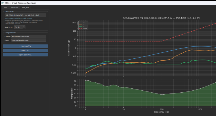
Figure 7 — Pass/Fail chart. Three channels (x/y/z) vs MIL-STD-810H Mid-field limit (red dashed). All channels are well within spec: the margin subplot (bottom) shows 30–60 dB positive margin throughout the full frequency range.
Top panel — SRS vs Limit
Each channel plotted in a distinct colour. Limit curve: red dashed. Red fill = exceedance (SRS > limit). Orange fill = caution zone (0 ≤ margin < 3 dB).
Bottom panel — Margin (dB)
Margin M(f) = 20 × log₁₀( Limit(f) / SRS(f) )
| Colour |
Condition |
Meaning
|
| Green |
M ≥ 3 dB |
Well within specification
|
| Orange |
0 ≤ M < 3 dB |
Caution — low margin
|
| Red |
M < 0 dB |
FAIL — exceedance
|
Interactive cursor
Hover anywhere on either panel to see a floating readout snapped to the nearest frequency band, showing frequency, SRS value, limit value, margin in dB, and PASS/FAIL status. The readout border turns green, orange or red accordingly.
Verdict text
The result box below the chart shows global verdict, per-channel minimum margin, and the 10 worst exceedance frequencies. Example output:
PASS   —   Maximax SRS
Limit: MIL-STD-810H Meth.517 — Mid-field (0.5–1.5 m)

Per-channel result:
  PASS  x     min +42.1 dB @ 500 Hz
  PASS  y     min +38.7 dB @ 342 Hz
  PASS  z     min +45.3 dB @ 1000 Hz

Worst margin (all channels): +38.7 dB  @  342.0 Hz
No exceedance detected over the computed frequency range.
Export
| Button |
Output |
Content
|
| Export CSV… |
.csv |
Per-channel SRS · Worst SRS · Limit · Per-channel margin · Worst margin · Status. Header block includes curve name and scale factor for traceability.
|
| Export graph PNG… |
.png / .pdf |
Both panels at 150 dpi.
|
Calculation Reference
Shock Response Spectrum
The SRS is the peak response of a bank of Single Degree Of Freedom (SDOF) oscillators, each with a different natural frequency f_n, driven by a common base acceleration x(t):
z(t) + 2ζωₙz'(t) + ωₙ²z(t) = −x(t)
| Curve |
Definition |
Standard?
|
| Positive SRS |
maxt[ ωₙ² z(t) ] |
Supplementary
|
| Negative SRS |
maxt[ −ωₙ²z(t) ] |
Supplementary
|
| Maximax SRS |
max(Positive, Negative) |
Required by most norms
|
Smallwood Recursive Filter
The Smallwood (1981) filter avoids step-by-step numerical integration, giving an exact discrete-time equivalent with coefficients computed once per frequency:
| E = exp(−ζωₙΔt) K = ωd·Δt (ωd = ωₙ√(1−ζ²))
|
| b₀ = 1 − E·sin(K)/K b₁ = 2(E·sin(K)/K − E·cos(K)) b₂ = E² − E·sin(K)/K
|
| a₁ = 2E·cos(K) a₂ = −E²
|
| y[k] = b₀x[k] + b₁x[k−1] + b₂x[k−2] + a₁y[k−1] + a₂y[k−2]
|
All N natural frequencies are processed in a single forward pass through the signal using NumPy broadcasting — typically 50–100× faster than a frequency-by-frequency loop.
Frequency axis
Log-spaced at 1/n octave: f_k = f_min × 2^(k/n)
| Resolution |
Bands 1–10 000 Hz
|
| 1/3 octave |
40
|
| 1/6 octave |
80
|
| 1/12 octave (default) |
160
|
| 1/24 octave |
320
|
Q factor and damping
Q = 1/(2ζ) ↔ ζ = 1/(2Q)
| Q |
ζ |
Use
|
| 10 |
5 % |
Aerospace standard — MIL-STD-810, ECSS, NASA
|
| 50 |
1 % |
Lightly damped structures
|
| 5 |
10 % |
Rubber-mounted, heavily damped
|
Primary and Residual SRS
| Zone |
Signal segment |
Required by
|
| Primary |
[t_start → t_end] — the shock transient |
All norms
|
| Residual |
[t_end → end] — free vibration decay |
MIL-STD-810H §517, ECSS §8.4.3
|
Pseudo-velocity and pseudo-displacement
| Quantity |
Formula |
Unit (SA in m/s²)
|
| Pseudo-velocity |
SV(fn) = SA(fn) / (2π·fn) |
m/s
|
| Pseudo-displacement |
SD(fn) = SA(fn) / (2π·fn)² |
m
|
Multi-axis combination
| Method |
Formula |
Applied to |
Use case
|
| SRSS |
√(SA_x² + SA_y² + SA_z²) |
Maximax only |
Euclidean resultant, triaxial sensor
|
| Worst-case Envelope |
max(SA_x, SA_y, SA_z) at each f |
All types |
Space programmes (ECSS App. H)
|
Supported Input Units
| Unit |
Physical quantity |
Vel/Disp SRS available
|
| m/s², g |
Acceleration |
✔ Yes
|
| m/s, mm/s |
Velocity |
✘ No
|
| m, mm, µm |
Displacement |
✘ No
|
| N, kN |
Force |
✘ No
|
| V, mV |
Voltage |
✘ No
|
| Pa, N/m² |
Pressure |
✘ No
|
| rad/s, RPM |
Angular velocity |
✘ No
|
Glossary
| Term |
Definition
|
| SRS |
Shock Response Spectrum. Peak SDOF response as a function of natural frequency.
|
| Maximax |
Negative|). The absolute peak response — required by most norms.
|
| SDOF |
Single Degree Of Freedom. A mass–spring–damper system with one resonant frequency.
|
| Q factor |
Quality factor. Q = 1/(2ζ). Q = 10 is the universal aerospace standard.
|
| ζ |
Damping ratio. Fraction of critical damping. ζ = 5 % ↔ Q = 10.
|
| Primary SRS |
SRS over the shock transient [t_start, t_end].
|
| Residual SRS |
SRS on the post-shock free vibration [t_end, end].
|
| SRSS |
Square Root Sum of Squares: √(SRS_x² + SRS_y² + SRS_z²).
|
| Envelope |
Point-by-point max across channels at each frequency.
|
| Margin (dB) |
20·log₁₀(Limit/SRS). Positive → PASS, negative → FAIL.
|
| Padding |
Symmetric time margin added around the auto-detected shock zone.
|
| Pyroshock |
Shock from explosive devices: separation bolts, pyrocutters, pin pullers.
|
| .orm |
NVGate JSON channel metadata: sampling rate, unit, name.
|
| .ors |
NVGate binary signal: float32 little-endian samples, SI units.
|
| NVDrive |
OROS TCP protocol for programmatic communication with NVGate.
|
Appendix SRS Limit Curves — Normative Reference
This page documents all predefined SRS limit curves available in the SRS Tool.
Each curve is identified by a confidence level tag shown next to its name in the interface.
Confidence level indicators
| Tag |
Meaning |
What to expect
|
| [normative]
|
Curve taken directly from the published standard as an SRS specification.
|
Breakpoints are faithful to the document. Use for compliance testing.
|
| [approximate]
|
Standard defines a time-domain waveform (half-sine, sawtooth…), not an SRS.
|
The SRS envelope is computed from the pulse shape. For exact results, import the waveform and run compute_srs() on it.
|
| [indicative]
|
Levels depend on mounting position, equipment mass or mission profile, or the exact document version was not available.
|
Use as a first-pass estimate only. Always verify with the applicable programme document.
|
All curves use Q = 10 (damping ζ = 5 %) and acceleration units (g).
Between breakpoints, interpolation is log-log linear (constant dB/octave slope).
Summary table
| Standard |
Sector |
Tag |
Application |
Peak level |
Freq. range
|
| NASA GEVS 2500 g |
Space |
normative |
Hardware on primary structure |
2 500 g |
20–10 000 Hz
|
| NASA GEVS 1000 g |
Space |
normative |
Hardware on panel or bracket |
1 000 g |
20–10 000 Hz
|
| NASA GEVS 3750 g (Qual.) |
Space |
normative |
Qualification unit (dedicated test article) |
3 750 g |
20–10 000 Hz
|
| Ariane 5 Equipment Bay |
Space |
indicative |
Satellite equipment bay, component level |
2 000 g |
100–10 000 Hz
|
| Ariane 6 |
Space |
indicative |
All payload positions, component level |
1 600 g |
100–10 000 Hz
|
| VEGA-C |
Space |
indicative |
Small satellite missions, component level |
1 200 g |
100–10 000 Hz
|
| ECSS-E-ST-10-03C Protoqual. |
Space |
indicative |
European space programmes, proto-qualification |
2 000 g |
20–10 000 Hz
|
| MIL-STD-810H M517 Near-field |
Military / Pyro |
normative |
Equipment < 0.5 m from pyrotechnic source |
10 000 g |
100–10 000 Hz
|
| MIL-STD-810H M517 Mid-field |
Military / Pyro |
normative |
Equipment 0.5–1.5 m from pyrotechnic source |
1 000 g |
100–10 000 Hz
|
| MIL-STD-810H M517 Far-field |
Military / Pyro |
normative |
Equipment > 1.5 m from pyrotechnic source |
100 g |
100–10 000 Hz
|
| MIL-STD-810H M516 Functional 40 g |
Military / Mech |
approximate |
Functional shock — must operate before and after |
80 g (2×A) |
5–2 000 Hz
|
| MIL-STD-810H M516 Crash 40 g |
Military / Mech |
approximate |
Crash hazard — must not endanger personnel |
60 g |
5–2 000 Hz
|
| MIL-STD-810H M516 Bench 15 g |
Military / Mech |
approximate |
Bench handling — drops during maintenance |
30 g |
5–2 000 Hz
|
| MIL-S-901D Grade A |
Military / Naval |
indicative |
US Navy lightweight shipboard equipment (< 136 kg) |
2 000 g |
20–10 000 Hz
|
| MIL-S-901D Grade B |
Military / Naval |
indicative |
US Navy medium-weight equipment (136–2 268 kg) |
1 000 g |
20–10 000 Hz
|
| DO-160G Cat. B 6 g |
Aviation |
approximate |
Airborne equipment — operational flight shock |
12 g |
5–2 000 Hz
|
| DO-160G Cat. C 15 g |
Aviation |
approximate |
Avionics — bench handling during maintenance |
30 g |
5–2 000 Hz
|
| DO-160G Cat. D 20 g |
Aviation |
approximate |
Airborne equipment — crash / emergency landing |
40 g |
5–2 000 Hz
|
| DEF STAN 00-35 Cat. M |
European Defence |
indicative |
UK defence — general military ground equipment |
1 000 g |
10–10 000 Hz
|
| DEF STAN 00-35 Cat. P |
European Defence |
indicative |
UK defence — aircraft store / weapon release |
2 000 g |
100–10 000 Hz
|
| GAM EG-13 Choc sévère |
European Defence (DGA) |
indicative |
French military — pyrotechnic devices, ejection seats |
2 000 g |
20–10 000 Hz
|
| GAM EG-13 Choc modéré |
European Defence (DGA) |
indicative |
French military — vehicle impacts, transport drops |
500 g |
10–5 000 Hz
|
| STANAG 4370 AECTP-201 M417 |
NATO |
indicative |
NATO — pyroshock, severity level 3 |
2 000 g |
100–10 000 Hz
|
| STANAG 4370 AECTP-201 M403 |
NATO |
approximate |
NATO — mechanical shock, severity level 3 |
50 g |
5–2 000 Hz
|
| IEC 60068-2-27 15 g / 11 ms |
Industrial |
approximate |
General industrial / commercial equipment qualification |
30 g |
5–2 000 Hz
|
| IEC 60068-2-27 50 g / 11 ms |
Industrial |
approximate |
Rugged industrial equipment — severe shock |
100 g |
5–2 000 Hz
|
| IEC 60068-2-27 100 g / 6 ms |
Industrial |
approximate |
Harsh shock environments — impacts, sudden accelerations |
200 g |
5–2 000 Hz
|
| IEC 61373 Cat.1 Class B |
Railway |
approximate |
Railway — equipment mounted on vehicle body (interior) |
6 g |
2–2 000 Hz
|
| IEC 61373 Cat.1 Class A |
Railway |
approximate |
Railway — bogie-mounted equipment (running gear) |
15 g |
2–2 000 Hz
|
| IEC 61373 Cat.2 Under-body |
Railway |
approximate |
Railway — under-body / axle-box mounted equipment |
50 g |
2–2 000 Hz
|
How the SRS Tool uses these curves
- Select a curve in the Pass/Fail tab.
- The tool interpolates the curve at the same frequency resolution as the measured SRS using log-log linear interpolation.
- Margin is computed point-by-point: Margin (dB) = 20 × log₁₀(limit / SRS)
- The overall result is PASS only if the margin is positive at all frequencies.
Adding a custom curve
You can import your own limit curve via a two-column CSV file (frequency Hz, level g) using the Load CSV button in the Pass/Fail tab. The SRS Tool applies the same log-log interpolation as built-in curves.
Algorithm: D.O. Smallwood, An Improved Recursive Formula for Calculating Shock Response Spectra, Shock and Vibration Bulletin, 1981. ·
Standards referenced: MIL-STD-810H (2019) · ECSS-E-ST-10-03C (2012) · NASA-STD-7003A (2011) · DEF-STAN 00-35 Part 3 (2021).


