Difference between revisions of "Modal First steps"
| (6 intermediate revisions by 3 users not shown) | |||
| Line 1: | Line 1: | ||
[[category:Modal]] | |||
Modal test and analysis is used to determine the engineering structures<nowiki>’</nowiki> modal parameters, such as modal frequencies, damping ratios, and mode shapes. The measured excitation and response (or only response) data are utilized in modal analysis, and then dynamic signal analysis and modal parameters identification are processed. The modal test and analysis has been developed for more than three decades, and much progresses have been made. It has been widely applied to the engineering filed, such as the dynamic design, manufacture and maintenance, vibration and noise reduction, vibration control, condition monitoring, fault detection, model updating and model validation. | |||
===Operating Deflection Shape=== | |||
Operating Deflection Shape (ODS) is the simplest way to see how a machine or structure moves during its operation, at a specific frequency or moment in time. There are two types of ODS: time domain ODS (TD ODS) and frequency domain ODS (FD ODS). | |||
TD ODS is based on the multi-channel time history data acquired spatially from a machine or structure. It shows the vibration motion of the machine or structure in a period of time clearly, just like a recorder. You can view a structure<nowiki>’</nowiki>s overall motion, and the motion of one part relative to another. Locations of excessive vibration are easily identified.<br><br>FD ODS is based on the frequency response functions (FRFs) or power spectral density functions (PSDs), which can be estimated from multi-channel time history data acquired spatially from a machine or structure. It shows how a structure behaves at a single frequency, helping you to find whether or not a resonance is being excited. In the OROS Modal, you even be allowed to inside the different behaves of repeated frequencies. | |||
===Experimental Modal Analysis=== | |||
In the Experimental Modal Analysis (EMA), the structures are excited by artificial forces, then both the inputs (excitation) and outputs (response) are measured to get the frequency response functions (FRFs) or impulse response functions (IRFs) by digital signal processing. Modal parameters can be identified from FRFs or IRFs by identification algorithms in frequency domain or time domain. EMA tests are usually carried out in the lab, with the advantage of high SNR (Signal to Noise Ratio) and easy to change test status. | |||
EMA identification methods can be classified into time domain (TD) methods and frequency domain (FD) methods according to different identification domain. Also they can be classified into SISO (single input single output), SIMO (single input multiple output), and MIMO (multiple input multiple output) according to different number of input and output. | |||
The FRFs are generally utilized for the EMA in frequency domain, which are estimated from the excitation and response signals. Then the modal parameters are identified by constructing the parametric or nonparametric models of the FRFs and and curve fitting them. While the IRFs are generally utilized for the EMA in time domain, which can be obtained the inverse FFT of FRFs. | |||
Time domain methods are suitable for the global analysis in a broad frequency band, which have good numeric stability. However, there are some limitations too: (1) very difficult to confirm the order of math model, (2) always time consuming, (3) many calculation modes got with the structural modes, and difficult to delete them, (4) many setting and judgment needed, complicated-to-use, (5) not able to taking account of the influence of out-band modes. Contrarily, frequency domain methods are always reliable, rapid, easy-to-use, with the capacity to consider the out-band modes and analysis uneven spaced FRFs, so they are applied widely. | |||
===Operational Modal Analysis=== | |||
Operational Modal Analysis is used for large civil engineering structures, operating machinery or other structures, making use of their output response only. These structures are always loaded by natural loads that cannot easily be controlled and measured, for instance waves loads (offshore structures), wind loads (Buildings) or traffic loads (bridges). | |||
Compared with EMA, OMA has its outstanding advantages. In OMA the structure studied is excited by natural loads instead of some expensive excitation equipments as used in EMA. In fact it is very difficult to excite large structures by artificial means. So OMA is more economic and fast, and endowed by nature with characteristics of multiple-input / multiple-output (MIMO). It could be used to distinguish closely coupled modes. Moreover, all the measured responses come under operational state of structures, and their real dynamic characteristics in operation could be revealed, so OMA is very suitable for health monitoring and damage detection of large-scale structures. | |||
Because there are limited channels and accelerometers in a data acquisition system, you may need to decide how to distribute the many measurement points in several groups, the so-called setups. For each setup you should keep 1 or more accelerators at the same location, which are called reference points. The reference points should be located far away the nodal points of the mode shapes. It is recommended to set 2 or 3 reference points. | |||
===Modal software features=== | |||
* Running on the current mainstream Operating systems: Windows 2000/XP/2003 Server/Vista | |||
* Coding with VC<nowiki>++</nowiki> language and object oriented programming technique, easy to be maintained and expanded | |||
* Four powerful functions: geometry modeling, project management, dynamic signal processing, and modal analysis | |||
* Convenient data importing interface, not only for time domain signal, but also frequency domain signal | |||
* Direct data acquisition from OR3x series analyzers, performing a modal test easily and rapidly | |||
* Various data format: Modal standard file format, Universal File Format (UFF) and OROS format (res, oxf, or oxl) | |||
* Integrated functions for geometry modeling | |||
** Import geometry from UFF or IGES files | |||
** Export geometry to UFF files | |||
** Create regular 3D geometry objects | |||
** Create and edit geometry interactively | |||
** Undo and redo operations for geometry edit | |||
** Customized geometry library | |||
* Combined with all kinds of data acquisition systems or dynamic signal analyzers to make up advanced modal analysis systems | |||
* Powerful, effective and easy-to-use signal processing based on wizard setting | |||
** Detrend, decimation and digital filter | |||
** Customized FFT parameters: FFT length, average times, and overlap percent | |||
** All kinds of window function: boxcar, hanning, hamming, flattop, exponential, force and so on | |||
** Power Spectrum Density (PSD) estimation: Auto PSD, Cross PSD, PSD matrix, using Welch<nowiki>’</nowiki>s averaged periodogram technique | |||
** Single input / multiple output (SIMO) FRF estimation: H1, H2 and Hc methods | |||
** Multiple input / multiple output (MIMO) FRF estimation with multiple coherence function | |||
** The signal processing is reversible | |||
* Dealing with not only traditional Experimental Modal Analysis (EMA), but also Operational Modal Analysis (OMA) | |||
* EMA techniques based on both input (excitation force) and output response | |||
** Select-band SIMO modal analysis technique: SIMO rational fraction orthogonal polynomial (RFOP), to obtain several modes from a selected frequency band by one identification | |||
** Narrow-band MIMO modal analysis technique, MIMO complex mode indicator function (CMIF), to identify modes one by one | |||
** Select-band MIMO modal analysis technique: frequency domain poly-reference (FDPR) and MIMO rational fraction orthogonal polynomial (RFPM), to obtain several modes from a selected frequency band by one identification | |||
** Broad-band MIMO modal analysis technique: EMA broad band frequency domain (EBFD) , to obtain many modes from a broad frequency band by one identification, or even obtain all the modes from the full frequency band by one identification | |||
** MIMO analysis methods: with capacity to identify heavy close or even repeated modes, ideal methods for experimental modal analysis of large and complicated structures | |||
** Single reference (SR) and Multiple References (MR) hammer impact modal analysis techniques | |||
* OMA techniques base on output data only | |||
** Valuable for the large civil engineering structures, operating machinery or other structures which are not easily excited artificially; cheap and fast, without requirement for excitation equipment; able to get the dynamic characters of structures in real operating conditions | |||
** Narrow-band operational modal analysis technique: frequency spatial domain decomposition (FSDD), to obtain modes one by one from the full output spectrum matrix | |||
** Narrow-band operational modal analysis technique: complex mode indicator function (CMIF), sharing the same algorithm with EMA Narrow-band, to obtain modes one by one from the half output spectrum matrix | |||
** Broad-band operational modal analysis technique: OMA broad band frequency domain (OBFD), to obtain many modes from a broad frequency band of the half output spectrum matrix by one identification, or even obtain all the modes from the full frequency band by one identification | |||
* Adopting mode indicator function (MIF) to indicate the existence of structural modes | |||
* Unlimited number of identified modes | |||
* Flexible interface arrangement and various mouse and hotkey operation, thereby greatly improving work efficiency | |||
* Perfect and friendly function for arranging interface, operating and exporting data | |||
** Multiple language interface: English and Chinese are available, and it<nowiki>’</nowiki>s convenient to develop other language interface | |||
** Special 2D and 3D graphic control panes, supplemented with other control modes such as mouse, hotkey, and menu operations | |||
** Flexible 2D curves display and control: showing or hiding gridlines, legends and other components, providing complete measurement information (measurement node, direction, whether driving point or not, and so ) of each plot | |||
** Multiple curve expressions: magnitude (linear, log, and dB coordinate), phase, unwrapped phase, real part, imaginary part, and Nyquist | |||
** Flexible 3D graphics display and control: showing or hiding node ID, input / output tags, axis and other components, freely translating, zooming and rotating the object | |||
** Top, bottom, left, right, front and back view of 3D objects, rendering in the style of frame lines or surface | |||
** Animation control based on OpenGL: play, stop, previous/next frame, amplitude and speed control functions | |||
** Exporting the modal results to text or graph | |||
** Directly saving all the curves or graphics to BMP or JPG files | |||
** Exporting the mode animation to AVI media files, convenient to generate multimedia presentation | |||
==First steps== | ==First steps== | ||
| Line 4: | Line 81: | ||
===Modal software first description=== | ===Modal software first description=== | ||
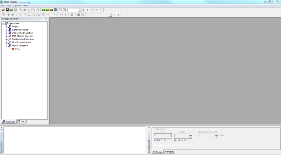
When | When Modal is launched, the following window appears for a few seconds. | ||
[[Image: | [[Image:image_2021-03-03_101236.png|framed|none]] | ||
Then the following window is displayed. | |||
[[Image:Modal_Manual_17.png|framed|none]] | [[Image:Modal_Manual_17.png|framed|none]] | ||
Click on <nowiki>’</nowiki>file<nowiki>’</nowiki> in the menu toolbar and on <nowiki>’</nowiki>open workspace<nowiki>’</nowiki>. | Click on <nowiki>’</nowiki>file<nowiki>’</nowiki> in the menu toolbar and then click on <nowiki>’</nowiki>open workspace<nowiki>’</nowiki>. | ||
For the first time you can open one of existing projects installed | For the first time, you can open one of the existing projects installed in the directory <nowiki>’</nowiki>C:\OROS\Programs\Modal\Examples<nowiki>’</nowiki>. | ||
There are: | There are: | ||
- 4 | - 4 projects for Experimental Modal Analysis | ||
- 2 | - 2 projects for Operational Modal Analysis | ||
[[Image:Modal_Manual_18.png|framed|none]] | [[Image:Modal_Manual_18.png|framed|none]] | ||
[[Image: | [[Image:image_2021-03-04_111358.png|framed|none]] | ||
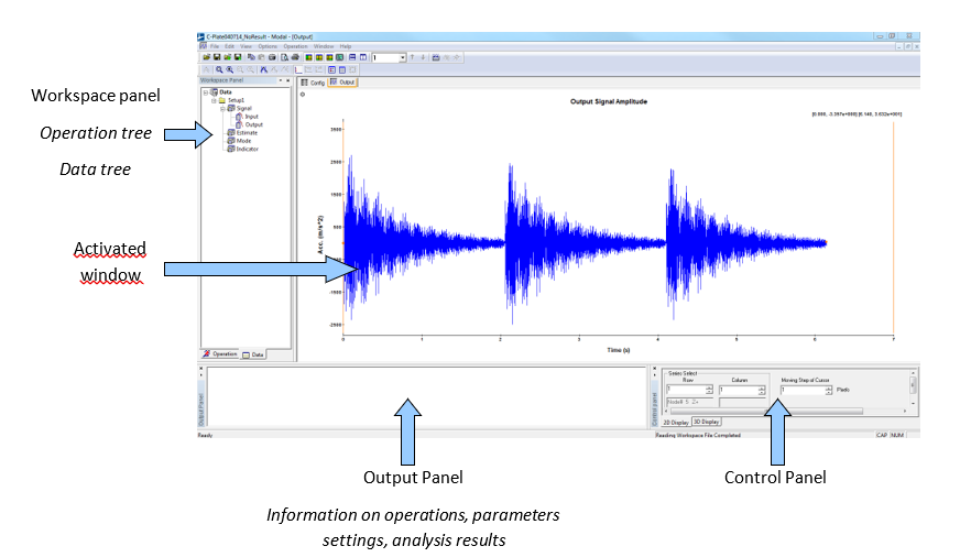
The | The main interface of the software is displayed as below, which includes four panels. | ||
[[Image:Modal_Manual_20.png|framed|none]] | [[Image:Modal_Manual_20.png|framed|none]] | ||
| Line 35: | Line 110: | ||
## an operation tree organized as a wizard to follow the different steps of a modal analysis | ## an operation tree organized as a wizard to follow the different steps of a modal analysis | ||
## a data tree where you can | ## a data tree where you can find all the data and results imported or calculated in the opened project. | ||
'''Activated window''' can display: | '''Activated window''' can display: | ||
| Line 44: | Line 119: | ||
'''Output Panel''' displays the last calculated results. | '''Output Panel''' displays the last calculated results. | ||
'''Control Panel''' contains | '''Control Panel''' contains different commands and functions respectively useful for 2D and 3D windows. | ||
===To know more=== | |||
To discover the different functions of this software, please refer to the <nowiki>’</nowiki>Getting Started Manual<nowiki>’</nowiki> by clicking on "Help -> Getting Started...". You can follow the various steps described in the document to obtain results very quickly. | |||
The online help embedded within the software can help you and also be consulted for all kinds of questions. | |||
==Environment== | ==Environment== | ||
Latest revision as of 11:26, 4 March 2021
Modal test and analysis is used to determine the engineering structures’ modal parameters, such as modal frequencies, damping ratios, and mode shapes. The measured excitation and response (or only response) data are utilized in modal analysis, and then dynamic signal analysis and modal parameters identification are processed. The modal test and analysis has been developed for more than three decades, and much progresses have been made. It has been widely applied to the engineering filed, such as the dynamic design, manufacture and maintenance, vibration and noise reduction, vibration control, condition monitoring, fault detection, model updating and model validation.
Operating Deflection Shape
Operating Deflection Shape (ODS) is the simplest way to see how a machine or structure moves during its operation, at a specific frequency or moment in time. There are two types of ODS: time domain ODS (TD ODS) and frequency domain ODS (FD ODS).
TD ODS is based on the multi-channel time history data acquired spatially from a machine or structure. It shows the vibration motion of the machine or structure in a period of time clearly, just like a recorder. You can view a structure’s overall motion, and the motion of one part relative to another. Locations of excessive vibration are easily identified.
FD ODS is based on the frequency response functions (FRFs) or power spectral density functions (PSDs), which can be estimated from multi-channel time history data acquired spatially from a machine or structure. It shows how a structure behaves at a single frequency, helping you to find whether or not a resonance is being excited. In the OROS Modal, you even be allowed to inside the different behaves of repeated frequencies.
Experimental Modal Analysis
In the Experimental Modal Analysis (EMA), the structures are excited by artificial forces, then both the inputs (excitation) and outputs (response) are measured to get the frequency response functions (FRFs) or impulse response functions (IRFs) by digital signal processing. Modal parameters can be identified from FRFs or IRFs by identification algorithms in frequency domain or time domain. EMA tests are usually carried out in the lab, with the advantage of high SNR (Signal to Noise Ratio) and easy to change test status.
EMA identification methods can be classified into time domain (TD) methods and frequency domain (FD) methods according to different identification domain. Also they can be classified into SISO (single input single output), SIMO (single input multiple output), and MIMO (multiple input multiple output) according to different number of input and output.
The FRFs are generally utilized for the EMA in frequency domain, which are estimated from the excitation and response signals. Then the modal parameters are identified by constructing the parametric or nonparametric models of the FRFs and and curve fitting them. While the IRFs are generally utilized for the EMA in time domain, which can be obtained the inverse FFT of FRFs.
Time domain methods are suitable for the global analysis in a broad frequency band, which have good numeric stability. However, there are some limitations too: (1) very difficult to confirm the order of math model, (2) always time consuming, (3) many calculation modes got with the structural modes, and difficult to delete them, (4) many setting and judgment needed, complicated-to-use, (5) not able to taking account of the influence of out-band modes. Contrarily, frequency domain methods are always reliable, rapid, easy-to-use, with the capacity to consider the out-band modes and analysis uneven spaced FRFs, so they are applied widely.
Operational Modal Analysis
Operational Modal Analysis is used for large civil engineering structures, operating machinery or other structures, making use of their output response only. These structures are always loaded by natural loads that cannot easily be controlled and measured, for instance waves loads (offshore structures), wind loads (Buildings) or traffic loads (bridges).
Compared with EMA, OMA has its outstanding advantages. In OMA the structure studied is excited by natural loads instead of some expensive excitation equipments as used in EMA. In fact it is very difficult to excite large structures by artificial means. So OMA is more economic and fast, and endowed by nature with characteristics of multiple-input / multiple-output (MIMO). It could be used to distinguish closely coupled modes. Moreover, all the measured responses come under operational state of structures, and their real dynamic characteristics in operation could be revealed, so OMA is very suitable for health monitoring and damage detection of large-scale structures.
Because there are limited channels and accelerometers in a data acquisition system, you may need to decide how to distribute the many measurement points in several groups, the so-called setups. For each setup you should keep 1 or more accelerators at the same location, which are called reference points. The reference points should be located far away the nodal points of the mode shapes. It is recommended to set 2 or 3 reference points.
Modal software features
- Running on the current mainstream Operating systems: Windows 2000/XP/2003 Server/Vista
- Coding with VC++ language and object oriented programming technique, easy to be maintained and expanded
- Four powerful functions: geometry modeling, project management, dynamic signal processing, and modal analysis
- Convenient data importing interface, not only for time domain signal, but also frequency domain signal
- Direct data acquisition from OR3x series analyzers, performing a modal test easily and rapidly
- Various data format: Modal standard file format, Universal File Format (UFF) and OROS format (res, oxf, or oxl)
- Integrated functions for geometry modeling
- Import geometry from UFF or IGES files
- Export geometry to UFF files
- Create regular 3D geometry objects
- Create and edit geometry interactively
- Undo and redo operations for geometry edit
- Customized geometry library
- Combined with all kinds of data acquisition systems or dynamic signal analyzers to make up advanced modal analysis systems
- Powerful, effective and easy-to-use signal processing based on wizard setting
- Detrend, decimation and digital filter
- Customized FFT parameters: FFT length, average times, and overlap percent
- All kinds of window function: boxcar, hanning, hamming, flattop, exponential, force and so on
- Power Spectrum Density (PSD) estimation: Auto PSD, Cross PSD, PSD matrix, using Welch’s averaged periodogram technique
- Single input / multiple output (SIMO) FRF estimation: H1, H2 and Hc methods
- Multiple input / multiple output (MIMO) FRF estimation with multiple coherence function
- The signal processing is reversible
- Dealing with not only traditional Experimental Modal Analysis (EMA), but also Operational Modal Analysis (OMA)
- EMA techniques based on both input (excitation force) and output response
- Select-band SIMO modal analysis technique: SIMO rational fraction orthogonal polynomial (RFOP), to obtain several modes from a selected frequency band by one identification
- Narrow-band MIMO modal analysis technique, MIMO complex mode indicator function (CMIF), to identify modes one by one
- Select-band MIMO modal analysis technique: frequency domain poly-reference (FDPR) and MIMO rational fraction orthogonal polynomial (RFPM), to obtain several modes from a selected frequency band by one identification
- Broad-band MIMO modal analysis technique: EMA broad band frequency domain (EBFD) , to obtain many modes from a broad frequency band by one identification, or even obtain all the modes from the full frequency band by one identification
- MIMO analysis methods: with capacity to identify heavy close or even repeated modes, ideal methods for experimental modal analysis of large and complicated structures
- Single reference (SR) and Multiple References (MR) hammer impact modal analysis techniques
- OMA techniques base on output data only
- Valuable for the large civil engineering structures, operating machinery or other structures which are not easily excited artificially; cheap and fast, without requirement for excitation equipment; able to get the dynamic characters of structures in real operating conditions
- Narrow-band operational modal analysis technique: frequency spatial domain decomposition (FSDD), to obtain modes one by one from the full output spectrum matrix
- Narrow-band operational modal analysis technique: complex mode indicator function (CMIF), sharing the same algorithm with EMA Narrow-band, to obtain modes one by one from the half output spectrum matrix
- Broad-band operational modal analysis technique: OMA broad band frequency domain (OBFD), to obtain many modes from a broad frequency band of the half output spectrum matrix by one identification, or even obtain all the modes from the full frequency band by one identification
- Adopting mode indicator function (MIF) to indicate the existence of structural modes
- Unlimited number of identified modes
- Flexible interface arrangement and various mouse and hotkey operation, thereby greatly improving work efficiency
- Perfect and friendly function for arranging interface, operating and exporting data
- Multiple language interface: English and Chinese are available, and it’s convenient to develop other language interface
- Special 2D and 3D graphic control panes, supplemented with other control modes such as mouse, hotkey, and menu operations
- Flexible 2D curves display and control: showing or hiding gridlines, legends and other components, providing complete measurement information (measurement node, direction, whether driving point or not, and so ) of each plot
- Multiple curve expressions: magnitude (linear, log, and dB coordinate), phase, unwrapped phase, real part, imaginary part, and Nyquist
- Flexible 3D graphics display and control: showing or hiding node ID, input / output tags, axis and other components, freely translating, zooming and rotating the object
- Top, bottom, left, right, front and back view of 3D objects, rendering in the style of frame lines or surface
- Animation control based on OpenGL: play, stop, previous/next frame, amplitude and speed control functions
- Exporting the modal results to text or graph
- Directly saving all the curves or graphics to BMP or JPG files
- Exporting the mode animation to AVI media files, convenient to generate multimedia presentation
First steps
Modal software first description
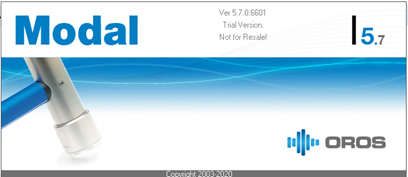
When Modal is launched, the following window appears for a few seconds.
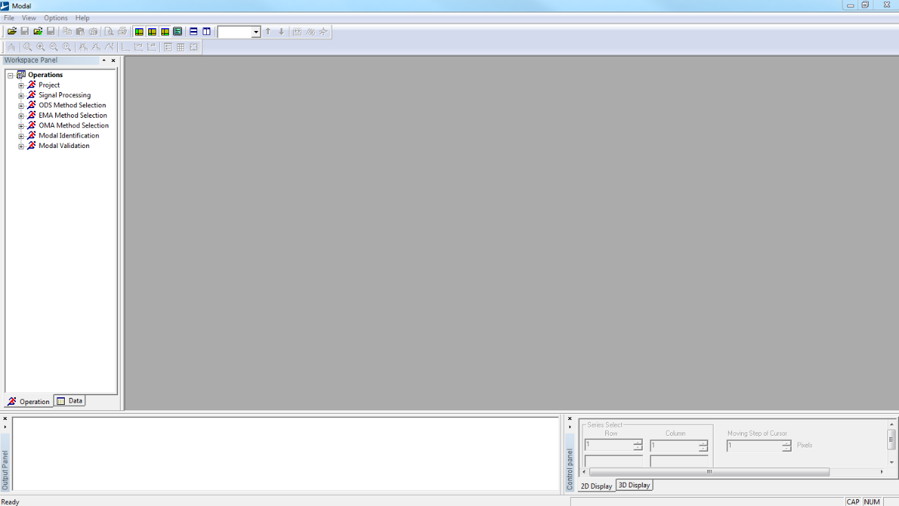
Then the following window is displayed.
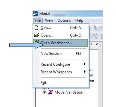
Click on ’file’ in the menu toolbar and then click on ’open workspace’.
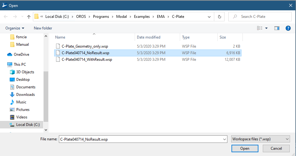
For the first time, you can open one of the existing projects installed in the directory ’C:\OROS\Programs\Modal\Examples’.
There are:
- 4 projects for Experimental Modal Analysis
- 2 projects for Operational Modal Analysis
The main interface of the software is displayed as below, which includes four panels.
Workspace panel contains:
- an operation tree organized as a wizard to follow the different steps of a modal analysis
- a data tree where you can find all the data and results imported or calculated in the opened project.
Activated window can display:
- 2D windows: time domain data, FRFs estimation, curve-fitting…
- 3D windows: geometry, mode shapes.
Output Panel displays the last calculated results.
Control Panel contains different commands and functions respectively useful for 2D and 3D windows.
To know more
To discover the different functions of this software, please refer to the ’Getting Started Manual’ by clicking on "Help -> Getting Started...". You can follow the various steps described in the document to obtain results very quickly.
The online help embedded within the software can help you and also be consulted for all kinds of questions.
Environment
General interface
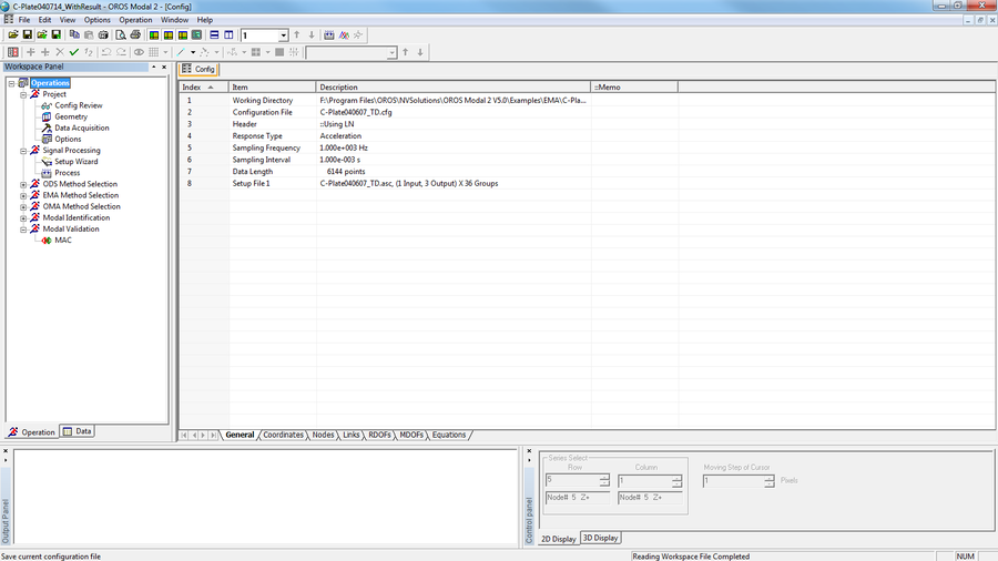
When Modal is running, the following interface will be displayed.
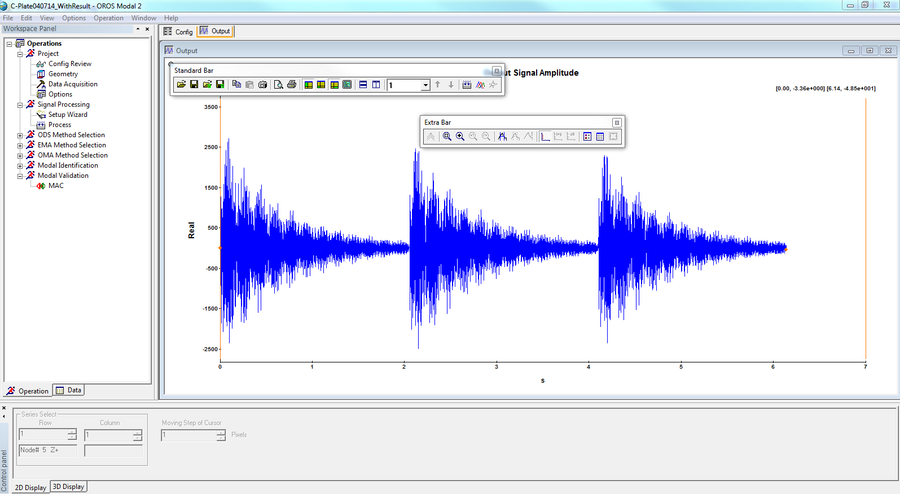
The menus, toolbars, workspace panel, output panel and control panel are listed from top to bottom. The center empty area of the interface is reserved for the main window. The workspace panel, output panel and control panel are generally called shortcut panels. The state bar locates in the bottom of window. The menus’ tips, processing bar and its tips are all showed on the state bar.
When you create a new configuration file or open a workspace file without measurement data, the ’Config’ window will first be shown.
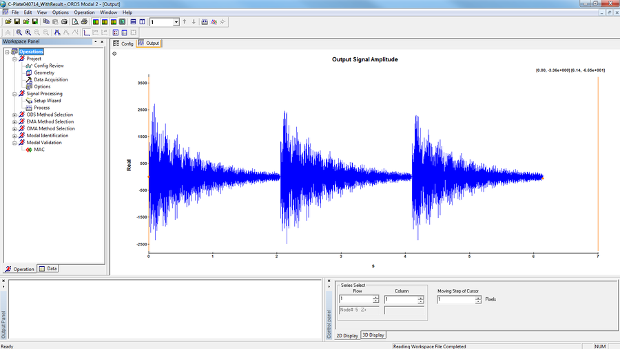
When users open a configuration file or workspace file with measurement data, the ’Output’ curve window will first be shown. There are two cursors on the left and right of the window respectively. The red point denotes the closest point to the cursor. The X and Y axes values of the two red points are shown dynamically on the top right corner of the window.
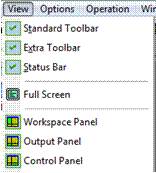
Each part of the interface can be shown or hidden through menu or toolbar operation. Users can also change the size or positions of each part by dragging the mouse.
Besides, all parts of the interface can be arranged to floating style for the purpose of getting more display space.
The software can also remember the adjusted interface style automatically in order to fit users’ habits.
