Difference between revisions of "NVGate Filter Builder"
(→Filter) |
|||
| Line 1: | Line 1: | ||
[[category:NVGate]] | [[category:NVGate]] | ||
====Filter==== | ====Filter==== | ||
Define | Define several IIR filters and select the modules to which the filters are applied. The filters operate on the time domain series, and they can be applied to various signal processing stages (Inputs, Plug-in channels, Outputs, Player tracks). | ||
[[Image:Filter_builder_02.png|framed|none]] | [[Image:Filter_builder_02.png|framed|none]] | ||
Revision as of 15:00, 4 December 2020
Filter
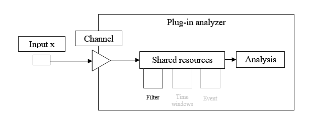
Define several IIR filters and select the modules to which the filters are applied. The filters operate on the time domain series, and they can be applied to various signal processing stages (Inputs, Plug-in channels, Outputs, Player tracks).
Connect filter
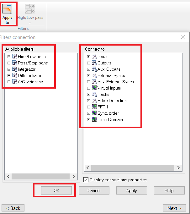
In the acquisition tab, The left button (Apply to) allows users to choose where to apply the filters. The right button (Filter builder) allows users to setup the properties of the filters.
![]() Apply to: This button opens the following dialog. To choose where to apply the filters, drag the selected filter on the left and drop it on the selected module on the right.
Apply to: This button opens the following dialog. To choose where to apply the filters, drag the selected filter on the left and drop it on the selected module on the right.
Then the filters connection properties will be displayed, and the properties of the selected filters and channels can be modified in this window.
Note: Due to the bandwidth compatibility, once a filter is applied to a module (ex: a plug-in channel), it can only be used to the same plug-in channels. The front-end is considered as a plug-in.
Filter builder
High-Low pass
![]() : Used to design a high-pass filter or a low-pass filter (Butterworth, Chebyshev Type I, and Chebyshev Type II).
: Used to design a high-pass filter or a low-pass filter (Butterworth, Chebyshev Type I, and Chebyshev Type II).
- Label: The name of the filter (by default High-Low pass n, with 1 ≤ n ≤ 4).
- Type: The type of the filter - Low pass or High pass.
- Design Type: The analog prototype filter - Butterworth, Chebyshev band-pass ripple (Type I), or Chebyshev stop-band ripple (Type II).
- Filter order: The filter order can be selected from 1 to 40 in Office mode, and from 1 to 10 in Connected mode. The higher the order is, the steeper the cut-off slope is.
- Applied to: Shows which plug-in the filter is applied to. The construction of the filter requires applying it to a signal with the same bandwidth. The determination of the associated plug-in/bandwidth is automatic. Deactivate the filter to reset.
- The other modules (front-end, monitor, resources) operate at the front end input sampling frequency (in connected mode on-line) or at the max player bandwidth (in post analysis mode).
| Apply to | Description |
| Front-end (20 kHz) | To be used on any resources and monitor |
| FFTx (10 kHz) | To be used on the FFT x analyzer only |
- Note that even if plug-ins run in the same bandwidth, it’s not possible to share filters between different plug-ins.
- Cut-off frequency: The cut-off frequency of the filter. The maximum value is the input frequency range FR. The minimum value is FR / 50000 in the Office mode, and FR / 40000 in the Connected mode.
- Warning: For measurements including the signal phase (i.e: balancing or Bode plot), the cut-off frequency must be chosen far from (at least 10 times) the frequency of interest. If not, the phase of the low pass filter will affect the phase of the result.
- By-pass: On / Off. The filter is not applied if By-pass is On.
By-passing a filter does not request stabilization time.
Pass-Stop band
![]() : Used to design a band-pass filter or a band-stop filter.
: Used to design a band-pass filter or a band-stop filter.
- Label: The name of the filter (by default Pass-Stop band n, with 1 ≤ n ≤ 4).
- Type: The type of the filter - Band pass or Band stop.
- Design type: The analog prototype filter - Butterworth, Chebyshev band-pass ripple (Type I), or Chebyshev stop-band ripple (Type II).
- Filter order: The filter order is 2*N, and N can be selected between 1 to 30 in the Office mode, and between 1 to 10 in the Connected mode. The higher the order is, the steeper the cut-off slope is.
- Applied to: Shows which plug-in the filter is applied to. The construction of the filter requires applying it to a signal with the same bandwidth. The determination of the associated plug-in/bandwidth is automatic. Deactivate the filter to reset.
- The other modules (front-end, monitor, resources) operate at the front end input sampling frequency (in connected mode on-line) or at the max player bandwidth (in post analysis mode).
| Apply to | Description |
| Front-end (20 kHz) | To be used on any resources and monitor |
| FFTx (10 kHz) | To be used on the FFT x analyzer only |
- Note that even if plug-ins run in the same bandwidth, it’s not possible to share filters between different plug-ins.
- Low cut-off frequency and High cut-off frequency: The low cut-off frequency of the filter flow and the high cut-off frequency of the filter fhigh. Their values need to meet the following conditions in the Office mode:
- flow ≥ 0.0001 * FR
- fhigh ≤ FR
- 0.0004 FR ≤ fhigh - flow ≤ 0.9998 * FR
- And in the Connected mode, the conditions become as below:
- flow ≥ 0.0005 * FR
- fhigh ≤ FR
- 0.000675 * FR ≤ fhigh - flow ≤ 0.99 * FR
- where FR is the input frequency range.
- By-pass: On / Off. The filter is not applied if By-pass is On.
Integrator
![]() : Used to design a time integrator filter associated with a high pass filter (to limit gain near DC components).
: Used to design a time integrator filter associated with a high pass filter (to limit gain near DC components).
- Label: the name of the filter (by default Integrator n, with 1 <= n <= ).
- Type: the type (High Pass + single integ. / High Pass + double integ.) of the filter.
- Applied to: Indicates on which plug-in the filter can be used. Indeed the construction of the filter requires applying it on signal with the same bandwidth. The determination of the associated plug-in/bandwidth is automatic. Deactivate the filter to reset it.
The other modules (front-end, monitor, resources) operate at the front end input sampling (in connected mode on-line) or to the max player bandwidth (in post analysis mode).
| Apply to | Description |
| Front-end (20 kHz) | To be used on any resources and monitor |
| FFTx (10 kHz) | To be used on the FFT x analyzer only |
- Note : Even if plug-ins run in the same bandwidth, it not possible to share filters between different plug-in.
- HP cut-off frequency: the cut-off frequency of the High pass filter contained in this integrator filter. Its maximum value is FR / 2000, and its minimum value is FR / 10000, where FR is the input frequency range.
Warning for measurements including signal phase (i.e: balancing or Bode plot) the cut-off frequency must be chosen far (10 times) from the frequency of interest. If not the phase of the low pas filter will affect the phase of the result.
'Integration 'time: the time constant of the integrator filter is equal to 1s. This is fixed value, not a setting.
The frequency response of a first order integrator filter is equal to:
- By-pass: On / Off. The filter is not applied if By-pass is On.
- Note : In post analyse, you will have a stabilisation time of 2 seconds before having any results or signal :
- The integrator filter has an integration time of 1s.
- This integrator filter also include a high pass filter. This filter needs also a stabilization time of 1s.
Therefore, the total stabilisation time of the filter is 2 seconds. Meanning the 2 first seconds of the signal will not be analysed.
Differentiator
![]() Used to setup a time differentiator filter associated with an exponential average to avoid that small fluctuations of the input signal become important distortions in the output signal.
Used to setup a time differentiator filter associated with an exponential average to avoid that small fluctuations of the input signal become important distortions in the output signal.
- Label: the name of the filter (by default Differentiator n, with 1 <= n <= 3).
- Applied to: Indicates on which plug-in the filter can be used. Indeed the construction of the filter requires applying it on signal with the same bandwidth. The determination of the associated plug-in/bandwidth is automatic. Deactivate the filter to reset it.
The other modules (front-end, monitor, resources) operate at the front end input sampling (in connected mode on-line) or to the max player bandwidth (in post analysis mode).
| Apply to | Description |
| Front-end (20 kHz) | To be used on any resources and monitor |
| FFTx (10 kHz) | To be used on the FFT x analyzer only |
Note even if plug-ins run in the same bandwidth, it no possible to share filters between different plug-in.
- Avg. duration:Filter average duration. By default, the average duration is equal to 0s. This value can be modified by the user. This setting is used to specify the exponential average duration of the differentiator filter
Xmean(n) = λX(n) + (1 – λ)Xmean(n-1) with Xmean(n) the averaged input signal at instant n, X(n) the input signal at instant n and λ the averaging factor.
The following formula is applied to the averaged signal:
Y(n) = (Xmean(n) -Xmean(n-1)) / fs. with, Y(n) the differentiated signal at instant n, Xmean(n) the averaged input signal at instant n and fs the sampling frequency.
- By-pass: On / Off. The filter is not applied if By-pass is On.


