Difference between revisions of "NVGate Torsional"
| Line 181: | Line 181: | ||
|} | |} | ||
Revision as of 18:00, 8 May 2020
Torsional
NVGate propos a comprehensive suite for torsional measurements and analyses. It addresses most of the torsional, cyclic and rotational resonances issues. For both R&D and diagnostics, the latest torsional feature the OROS analyzer the solution for transmissions, engines and electric machinery vibration analysis.
Overview
Frequency to RPM converter (Torsional inputs)
On reciprocating machinery (diesel engine, pump) or any acyclic rotating devices (generator,compressor), the cause of vibrations often comes from the non-linearity of the angular speed. The analysis of the instantaneous angular speed inside each shaft revolution provides essentialinformation. Such information are helpful for vibrations reduction during prototyping or evenfor source identification while doing service diagnostics.
The common way to measure such instantaneous velocity is to install a coding wheel or a rotary encoder on the shaft. Then the rate of pulse delivered by such device is directly proportional to the RPM speed during the last pulse interval. This type of measurement needs a specific conditioner(usually an external box) which transforms the pulses train in a continuous voltage proportional to the RPM.
Such devices are expensive, lead to more cable, are oftenlimited to 2 probes and so on. But the main inconvenience is the phase error they introducedue to their internal response time.
OROS propose an integrated frequency to RPM converter which avoids the above-mentioned inconveniences.
This option transforms each external Synch input in afrequency to RPM converter (allows handling up to 6 torsional/acyclic inputs at a time). This integrated converter benefits of the high accuracy of the 3-Series analyzers Ext. synch inputs (over sampled up to 6.4 MHz). As a matter of fact the sampling of such pulse rate must bevery accurate in order to avoid speed jitter on the result.
The ext. synch input can be used as a:
1. Trigger -> provides edge detection events
2. Conventional tachometer -> provides RPM at each
revolution.
3. Torsional converter (option) -> provides
instantaneous RPM as a signal.
By selecting the third option (Torsional) in the ModeSetting, the ext. synch is made available as a standard inputproviding the RPM signal.The other settings to update are:
· the number of pulses/rev.
· Average size which acts as rpm smother when the
jitter is too high.
· Min/max speed which operates the same as for the
other tachometers.
· The missing teeth (0, 1 or 2) will create virtual pulse
when detecting missing pulses (1or 2 consecutives)
Pulses train
Converted RPM
· At least the filter which let you integrate or differentiate the RPM speed to getrespectively plane angle deviations and angular accelerations for the analyses.
Analyses
The instantaneous signals are available for numerous analyses. The main ones are:
· The non cyclic behavior of a shaft which is analyzed by the order analysis processing providing order profiles and the time domain analysis for in revolution RPM profiles.
· The torsional behavior of a shaft (crankshaft, alternator) or a driving belt (service belt) being excited by its acyclic motion. In such a case the phenomena are analyzed order by order using the cross-phase tracking capabilities of the SOA Plug-in. In this case 2 or more torsional inputs are used: in different location of the shaft or on each pulley driven by the belt.
On-line
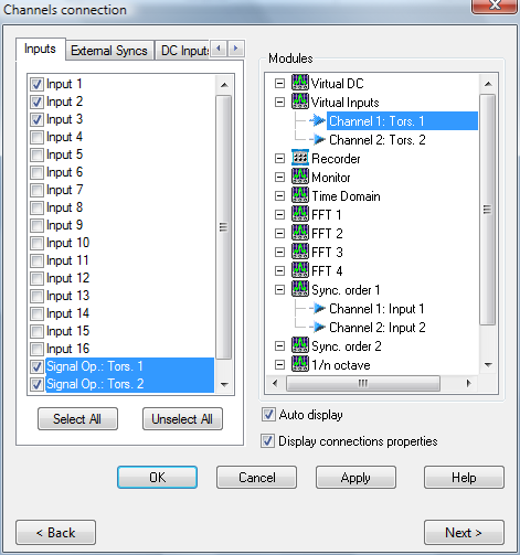
In the on-line mode the torsional inputs appear as additional in the channels connection dialog box. They are identified as Tors. x from the Signal Op. resource (not visible in the ASB). These signals can be dispatched exactly as the standard inputs ones; recorded, analyzed and monitored with the TDA plug-in. The torsional inputs may be recorded as it or the source pulses can be recorded also.
Post-processing=
For post-analysis purposes, the way to operate depends on the type of recorded signal: · If the converted signal (Tors x) have been recorded, the post analysis is exactly like for the usual recorded inputs: · if the pulses have been recorded and not the converted signal, a new resource module called Signal Operation is then available for this conversion.
· The conversion setup is available from the ASB. It is identical to the on-line one: · At least the Tors. x signal (converted to angular velocity (or acceleration or deviation) is available from the track connection dialog:
Specifications
The FVC option features the following main specifications:
· Number of pulses/rev: 1 to 4096
· Max pulse frequency: 40 kHz 64 times oversampled,
· Max angular speed:
Max RPM = (40 000*64)/pulse per revolution exemple : 12 800 RPM with 200 Pls/rev
· Missing teeth management: up to 3 consecutive teeth.
· Available filters: HP, LP; BP, SB, Int, double Int, differentiation
Angular sampling for SOA analysis
The major improvement comes as a simple setting… with large effects. Indeed the possibility to sample the measured signal with a distributed angle pulses of a rotating shaft provides accurate results.
This applies mainly on machineries which feature cyclic variation of their rotating speed. Main ones are:
- Engines (Diesel, Gas, 2/4 strokes)
- Reciprocating pumps or compressors
- Transmission (Torque damper, belt, shaft)
- Electric machines (generator, alternator, motor)
The angular sampling allows getting the exact angle (or phase) of the events in the machine cycle. The results are event better using the time domain averaging (i.e. angular).
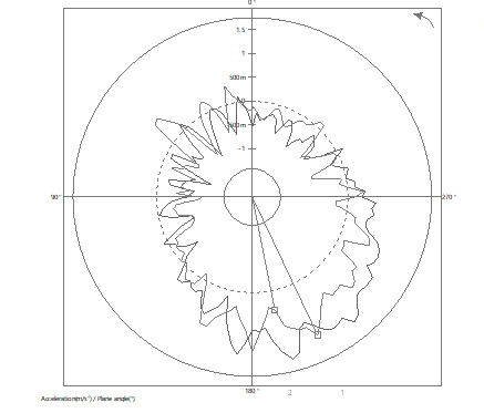
The following example shows the differences between a usual synchronous order analysis and the same one based on angular sampling. The phase differences are clearly visible especially on the ShaftView graphs.
With and without angular sampling Shaft view on an electric machinery bearing
Operations
In order to use the angular sampling function (Optional) it is necessary to have at least:
- A pulses train signal with a known number of pulses/rev
- phase reference (usually a 1 pulse/rev signal)
The sampling signal comes from an ext. synch input. The mode must be set to Sampling or any of the Sampling + xxx
It is necessary to associate a phase reference (the 0°) to the sampling pulse. It can be any tachometer or the sampling input itself. In this last case the 0° will be the first detected pulse or the missing pulse if there are some.
Then the Tachometer and the Sampling are assigned to a SOA plug-in.
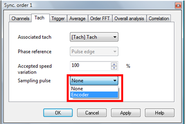
The Sampling pulse setting defines if the angular sampling is activated or not:
- If set to None, the SOA will works on the regular way: Interpolation of the sampling dates from the RPM information).
- If set to a sampling input, the SOA will use it for sampling the channels signals
Advantages of the OROS solution
The angular sampling is an old technique which used to be achieved by replacing the sampling clock by an encoder signal. Even if this procedure provides correct order and angles measurement it has a lot of defects. The technique provided by oros"" corrects these defects.
The following table compares the possible signal alteration and the OROS solution
| Traditional angular sampling | OROS angular sampling |
| Results are not alias free. It is not possible to apply anti aliasing as the sampling frequency is not known by the acquisition system. | Alias free results. The results are not affected by the alias frequencies thanks to the re-sampling technique. Indeed the analyzer acquires the sample at high freq. (102.4 kS/s) and then re-samples it with a tracking anti-aliasing filter. |
| The number of pulses/rev. must be a power of 2. Because the digital Fourier transform need a power of 2 samples, if you need to analyze it in order domain (n Revolutions) it is compulsory to deliver n² samples per revolution. | Any number of pulse/rev and any angular resolution are possible. The re-sampling technique used by the SOA allows interpolating the correct number of pulse (n²) from any acquire number of pulses |
| Missing pulses are not supported. Obviously the missing pulses will conduct to missing samples. | Missing pulses are supported. The OROS torsional measurement is able to interpolate and create the missing pulses. Then the complete pulse sequence is used by the re-sampling algorithm. |
NVGate V8.00 allows achieving angular sampled analysis avoiding the artifacts introduced by the direct angular sampling.
Twist measurements (static and dynamic)
The twist measurement consists of computing the angle between the 2 side of transmission shaft (or belt/chain). The measured angle is directly proportional to the stress and the applied torque. One common application is to choose an apropriate tortional damper.
The twist can be:
- Static twist: measure the transmitted torque and power. This is a parameter not for analysis
- Dynamic twist: measure the oscillating stress and resonances. This is a dynamic signal to be analyzed.
Both signals are computed simultaneously by the virtual input module.
When the torsional signals are settled up, simply connect it to the Virtual input plug-in
For computing the phase between the 2 sides of the twist it is necessary having a tachometer.
This tachometer can come from any of the inputs or directly from one of the torsional signals using the Torsional + tach. mode.
Then click on the Tools/Virtual inputs/dynamic button to open the virtual inputs setting. Click on the Twist tab. Select each torsional signal from the source 1 and source 2 lists.
The twist will be displayed in angle or torque. The coefficient is used to convert the read angle in torque.
The result are available from the add/Remove windows under the virtual input tab.
Note that the any number of pulses/rev can be used for twist computation and these numbers of pulses/rev can either be different on each side.
The following table describes the difference between classical twist measurement and the OROS one:
| Classical twist measurement | OROS twist |
| Twist measurement force having the same number of pulse on each side. The difference between the 2 signals is requiring the same number of sample/rev. | Twist support different number of pulse/rev signals. The OROS twist algorithm is based on phase computation rather than pulse timing comparison. Thanks to this the analysis is independent from the number of pulses/rev. |
| Twist measurement based on integration of the angular speed (torsional) is not stable | Twist signal is stable and do not diverge. Indeed the OROS Twist algorithm do not uses integration techniques |


