Difference between revisions of "NVGate Can BUS"
(Created page with "==CAN Bus== Car Area Network (CAN) bus is great source of data easily collected into vehicles, jet engines and power generation machineries. This Network provides real-time pa...") |
(No difference)
|
Revision as of 17:01, 8 May 2020
CAN Bus
Car Area Network (CAN) bus is great source of data easily collected into vehicles, jet engines and power generation machineries. This Network provides real-time parameters that can be used to correlate measurements and/or evaluate their influence. As an example, the correlation of noise and vibration with the engine load is a typical application of CAN parameter acquisition. For this application, the engine load is collected from the ECU through the CANBus.
Hardware
The hardware consists of an interface box which is adapted to the CAN-Bus impedance and a High speed serial cable (1 and 3 meters) connected to the new analyzer’s high speed serial port. When connected to a CAN-bus the parameter encoding has to be setup in the software allowing their collection by the hardware.
Connection
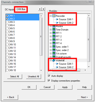
Then each CAN parameter is declared in the CAN input list. One CAN inputs corresponds to one parameter from the CAN bus. The CAN inputs are enabled like the DC inputs.
The CAN inputs operate likes DC inputs they can:
- Be recorded with the recorder plug-in
- Monitored by view meter or front end profiles
- Saved into profiles (waterfall)
- Used as waterfall's parameters
- Trigger level and delta level events
Up to 24 CAN parameters are available. Note that as the maximum recorded channels is 38, it is not possible to records all standards inputs (32 inputs + 4 aux. + 2 triggers) plus all CAN inputs (24 CAN parameters).
We are able to import CanBus .dbc file to automatically import the settings. Read his page.
CAN parameters configurations are saved in a model, workbook or project and are easily recalled for further utilization.
Can-Bus general Settings
When connected to a CAN-bus the parameter encoding has to be setup in the software allowing their collection by the hardware.
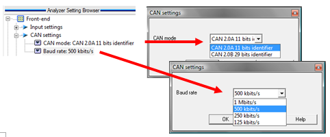
- CAN Mode: The Mode one defines the protocol to be used. Most of CAN bus uses 11 bits protocol.
- Baud Rate: The Baud rate one defines the speed of the bus. 500 Mb/s is the most common baud rate for automotive application.
Can-Bus input settings
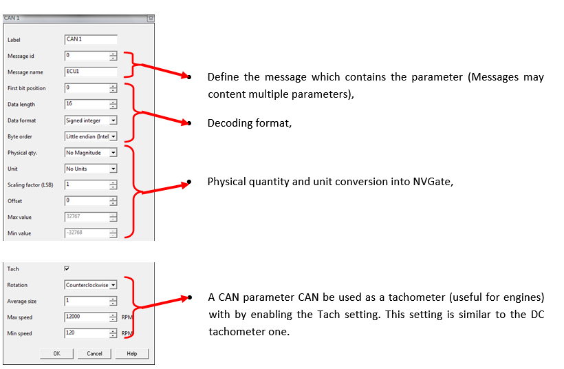
These sub-module contains all the settings related to the parametrics CAN inputs such as data type, parameters and sensitivity read from CAN interface. The CAN interface handle up to 24 different parameters. These format settings define where and how the parameter is encoded in one CAN message:
- Label: defines the name of this CAN input (by default CAN input n, with 1 <= n <= 24). The label of each CAN input is used in the result name and in all connection tools.
- Message ID: defines the ID of the message which contains the parameter
- Message NAME: defines the ID of the message which contains the parameter
- First bit position: defines the 1st position of the bit that contains the parameter
- Data length: defines the length of the data which contains the parameter
- Data Format: defines the format of the parameter if this is a "Signed Integer" or "Unsigned Integer"
- Byte order: defines the order of the byte to decode the parameter. This is either "Little endian (Intel)" or "Big endian (Motorola)"
- Physical qty.: defines the physical quantity of the reade value of parameter used to convert to NVGate data.
- Unit.: the Unit of the read value of parameter used to convert to NVGate data
- Scaling factor (LSB): define the scale factor conversion of the parameter to convert to NVGate data
- Offset: defines the offset compensation
Example:
Reading active gear:
Physical quantity: No Magnitude, Unit = No Unit,
Scaling factor (LSB) = 1, Offset = 0
Read Data = 2
NVGate value is: Read Data * Scaling factor (LSB) + Offset
NVGate value is: 2
Reading Acceleration in "g"
Physical quantity acceleration, Unit = Gravity (same as NVGate user Preferences)
Scaling factor (LSB) = 0.01, Offset = 0
Read Data = 1254
NVGate value is: Read Data * Scaling factor (LSB) + Offset
NVGate value is: 12.54g
- Max Value: defines the maximum value allowed for the parameter. This read only setting is automatically computed according to other setting parameters.
- Min Value: defines the minimum value allowed for the parameter. This read only setting is automatically computed according to other setting parameters.
- Tach: On / Off. Used to activate a digital tach whose source is this external sync.
- Rotation: Depending on the way you look at a measured shaft or on the convention you are using, the shaft may be considered as rotating clock wise or counter clock wise. This has noticeable impact on the phase of spectra and orders.
See Tachometers § for more details.
Hidden/fixed: Hidden if Tach is Off.
- Average size: defines the average number used to compute the average speed. Revolution number n average speed is: avrg_speed[n-1] + (inst_speed[n-1] - avrg_speed[n-1]) / avrg_size.
Hidden/fixed: Hidden if Tach is Off.
- Max speed: defines the highest measured angular speed. All revolutions with a speed higher than Max speed are rejected. By default Max speed is expressed in RPM.
The Max speed setting is also used:
- to specify the limit of Y axis of the RPM profile result
- to compute the limit of the maximum order of the SOA plug-in analyzer.
Hidden/fixed: Hidden if Tach is Off.
- Min speed: defines the lowest measured angular speed. All revolutions with a speed lower than Min speed are forced to 0 RPM. By default Min speed is expressed in RPM. The user can enter any value between Max speed / 1000 and Max speed. The max Min speed and min Min speed are defined according to the Max speed and Speed ratio.
Hidden/fixed: Hidden if Tach is Off.
import .dbc file
We are able to import CanBus .dbc file to automatically import the settings. Read this page.


