Difference between revisions of "NVGate Front End"
| Line 628: | Line 628: | ||
* '''Coupling''': the coupling of this external sync. | * '''Coupling''': the coupling of this external sync. | ||
[[ | [[NVGate_SOA_and_CBT_techniques#Tachometer_setup|This article compare the difference beetween coupling AC Vs DC for the tachometer phase.]] | ||
{|border="2" cellspacing="0" cellpadding="4" width="92%" align="left" | {|border="2" cellspacing="0" cellpadding="4" width="92%" align="left" | ||
Revision as of 13:49, 29 April 2020
Front-end
The Front-end module contains the settings that control the analyzer inputs, outputs, Ext Sync, and auxiliaries
Available results:
| Type | Size | Dimension | Domain | Save |
| Signal | 256 pt | 2D | time | Display only |
| DC | 1 pt | 1D | time | Display only |
| DC profile | 2048 pt max | 2D | time | Display only |
| RMS | 1 pt | 1D | Display only |
- Signal: The input time signal after sampling at the Input settings/ Input sampling rate
- DC: The DC input signal after sampling at the Input settings/ DC input sampling rate
- DC profile: Changes in the DC input signal during the Input settings/DC profile duration time
- Output Signal: The output signal
- Aux Output Signal: The auxiliary output signal
Input settings
The Input settings sub-module controls the Front-end general parameters that apply to all channels.
- High Input sampling and low Input sampling: the dynamic input/output sampling frequency (in Samples/second). Changing this will set the bandwidth for all plug-in analyzers and recorders to the following value: Sf / 2.56.
We allows the use of 2 different sampling rates for the dynamic inputs. It gathers inputs with the same physical quantity into groups, maintaining the same sampling into each group. When inputs are associated with the analysis plug-in, it adjusts its analysis bandwidth to match the inputs ones (except for SOA and overall acoustic plug in). Mixing input bandwidths in one analysis plug-in lead to set its bandwidth to the lowest one.
| Sampling frequency | Frequency range |
| 102.4 kS/s | 40 kHz bandwidth |
| 65.536 kS/s | 25.6 kHz bandwidth |
| 51.2 kS/s | 20 kHz bandwidth |
| 32.768 kS/s | 12.8 kHz bandwidth |
| 25.6 kS/s | 10 kHz bandwidth |
| 16.384 kS/s | 6.4 kHz bandwidth |
| 12.8 kS/s | 5 kHz bandwidth |
| 8.192 kS/s | 3.2 kHz bandwidth |
| 6.4 kS/s | 2.5 kHz bandwidth |
| 5.12 kS/s | 2 kHz bandwidth |
| 4.096 kS/s | 1.6 kHz bandwidth |
| 3.2768 kS/s | 1.28 kHz bandwidth |
| 3.2 kS/s | 1.25 kHz bandwidth |
| 2.048 kS/s | 800 Hz bandwidth |
- DC input sampling Optional, depends on hardware options: the sampling frequency (in Samples/second) = SF_Slow of DC Inputs (parametric). 2 sampling frequencies are proposed:
- 15 S/s
- 12.5 S/s.
These values may be adjusted to match the dynamic inputs sampling frequency submultiple. In both case the 10 Hz multiple (10 to 80 Hz) are rejected by a multi-notch filter
Note for V1 hardware, the following rejector are used:
| DC input sampling | Description |
| 15 S/s | The sampling frequency applied to the DC inputs is 15 samples/second, and the 50 Hz component of the signal is rejected at lower than -78dB |
| 12.5 S/s | The sampling frequency applied to the DC inputs is 12.5 samples/second, and the 50 Hz component of the signal is rejected at lower than -78dB |
- Note: the DC input sampling is available with the presence of optional DC inputs on OR35, OR36, OR38 and Mobi-Pack hardware only. With the OR36-V2, OR38-V2 and MP-V2, the parametric sampling of the universal input is automatically managed and not displayed. In this last case, the rejected frequencies are the harmonics of 10 Hz.
- DC profile duration*: the duration of the DC profile must be a multiple of 1/SF_Slow, with SF_Slow is the DC input sampling. Its minimum value is 10 / SF_Slow, and its maximum value is 2048 / SF_Slow.
- Inputs x-y 200V*: enables the 200V power supply on the corresponding block of 8 inputs LEMO connectors. There are up to 4 blocks of 8 inputs LEMO depending of the hardware configuration (input 1-8, input 9-16, input 17-24 and input 25-32)
- Check ICP: run an ICP check. The analyzer checks if an ICP transducer is correctly connected to each input for which the coupling is ICP. The analyzer checks the ICP connection by measuring DC polarization voltage through time averaging and opens a window with the results:
- short circuit: DC voltage < 4 V (the sensor may be faulty)
- ICP detected: DC voltage between 4 V and 20 V (an ICP sensor is detected)
- no connection: DC voltage > 20 V (no ICP sensor is detected), open circuit
- unstabilized input: DC voltage was not stabilized after 40 s.
- ICP current: Select the current injected in the inputs with active ICP coupling. The standard current is 4 mA. For super small transducer, the 4 mA * 28 V power dissipation increase dramatically the temperature transducer. This may be unsuitable with wax fixation (melting). The 2 mA ICP current allow dividing by 2 the transducer temperature.
- Detect TEDS: Run a TEDS detection. The analyzer detects if a TEDS transducer is connected to an input with the ICP TEDS coupling. All the characteristics of the transducer are detected and it automatically appears in the transducer database.
- Bridge Auto-zero: The Bridge Xpod features an automatic bridge balancing using voltage offset injection. The bridge balancing process duration is about 20 sec. Process information are provided in the NVGate status bar (bottom left). After balancing, the Offset compensation is modified according to the requested compensation voltage.
CAN Settings
Car Area Network (CAN) bus is great source of data easily collected into vehicles, jet engines and power generation machineries. This Network provides real-time parameters that can be used to correlate measurements and/or evaluate their influence. As an example, the correlation of noise and vibration with the engine load is a typical application of CAN parameter acquisition. For this application, the engine load is collected from the ECU through the CANBus.
The hardware consists of an interface box which is adapted to the CAN-Bus impedance and a High speed serial cable (1 and 3 meters) connected to the new analyzer’s high speed serial port. When connected to a CAN-bus the parameter encoding has to be setup in the software allowing their collection by the hardware.
- CAN Mode: The Mode one defines the protocol to be used. Most of CAN bus uses 11 bits protocol.
- Baud Rate: The Baud rate one defines the speed of the bus. 500 Mb/s is the most common baud rate for automotive application.
Remote Control
This module defines the content of some of the remote control (option) screens. The values of the following settings will configure the remote control display.
- Selected tach: The tach to be used for RPM display in the Rotating screens
- User field 1: The content of this setting (text) will be displayed in the upper user field of the remote control
- User field 2: The content of this setting (text) will be displayed in the lower user field of the remote control
User’s fields are useful to follows acquisition sequences. The content of the user field 1 &2 can be fulfilled by the sequencer, indicating the operator the point of impact or transducer position for ex.
Note the remote control is no more delivered with OROS analyzers.
Auto-ranging
Auto-ranging consists of making an automatic adjustment of the Input ranges to the levels of the signals present on input. It concerns only inputs for which the Enable auto-range is set to On. It can be done in two ways: Normal auto-range or Peak detection auto-range.
The normal auto-range must be used when the input signal level (Peak to peak) is stationary.
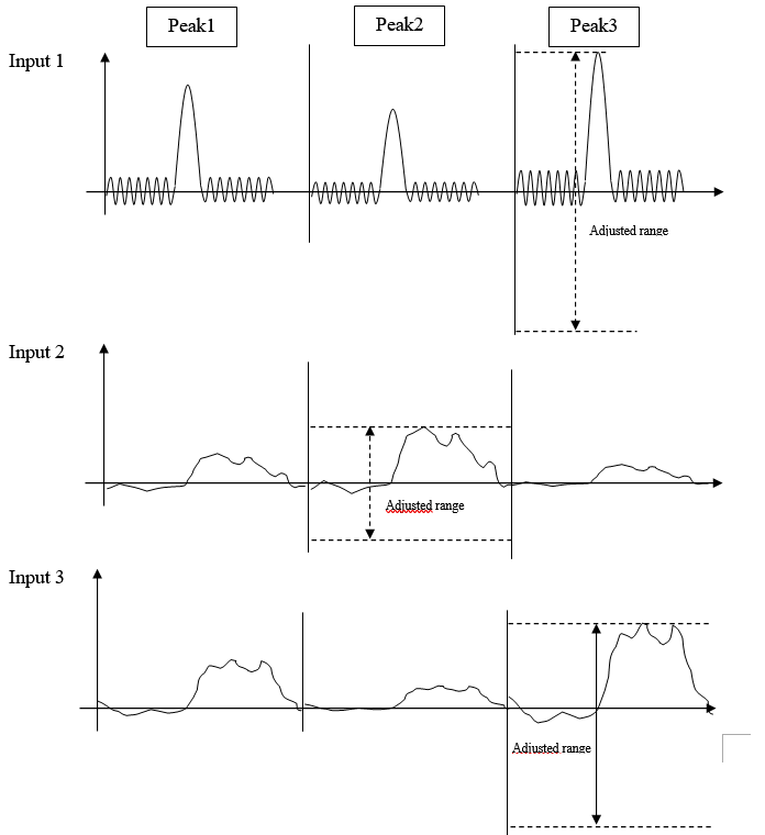
The peak detection auto-range must be used if there are spikes or large variations in the selected input. The computation takes into account (for all channels) data read during each spike of the selected input. This mode is useful if there are spikes in the selected input as in modal analysis, for example.
- Auto-range: button used to run the auto-range. If a Peak detection auto-range is running, the user can press this button to cancel the auto-range.
- Peak detection on: the input selected for peak detection (in a peak detection auto-range). If this value is "none", it is a normal auto-range. The list contains all the inputs for which the enable auto-range is set to On.
None: normal auto-range
Input x: auto-range on peak.
Auto-range starts when Input x amplitude value changes dramatically according to a defined factor (Edge detection).
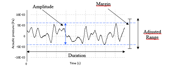
Margin: the margin in dB added to the max detected to determine the new range.
| Margin | Description |
| no | the max detected becomes the new range |
| 3 dB | add 3 dB to the max detected to compute the new range |
| 20 dB | add 20 dB to the max detected to compute the new range |
- Duration: duration of the normal auto-range.
Hidden/fixed: hidden in Peak detection auto-range mode.
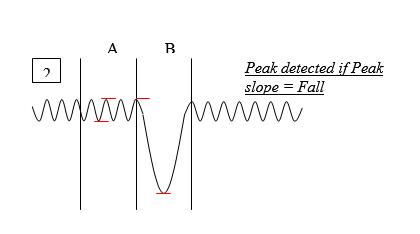
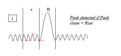
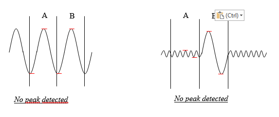
- Peak slope: the peaks are detected only with this slope.
Hidden/fixed: hidden in Normal auto-range mode.
| Peak slope | Description |
| Rise | Auto-range on a rising edge (1) |
| Fall | Auto-range on a falling edge (2) |
| Any | Auto-range on any edge (1 or 2) |
- Number of peaks: the number of peaks to detect in order to achieve the Peak detection auto range. It can vary from 1 to 10.
Hidden/fixed: hidden in Normal auto-range mode.
For example: Peak number = 3, Peak detection = input 1 and inputs 2 and 3 are connected to the analyzer and available for auto-ranging. The inputs 2 and 3 will be auto-ranged during the 3 peak detections and the maximum detected range will be kept for each input.
Peak detection with a hammer works well with a low sampling frequency (less than 13.8 kS/s). With higher sampling rate it may be difficult to detect the peaks.
- Edge detection: corresponds to the factor value that is used to detect the input x amplitude variations.
| Edge detection | Description |
| Low sensitivity | Factor = 100 |
| Normal | Factor = 20 |
| High sensitivity | Factor = 3 |
Hidden/fixed: hidden in Normal auto-range mode.
Expander modules
The XPod is a device that can be fixed on the OR362/OR382 side. Each XPod is associated to a block of 8 inputs.
In the connected mode, when and XPod is present each corresponding input can be routed to:
· The BNC input (Standard)
· The XPod connector
- Type: For acquisition setup preparation, the XPod presence can be simulated in the office mode:
One XPod type selector is available for each XPod position. This setting will include each new Xpod type according to their availability on the OROS catalog.
- Bridge max current: Select the max excitation current for the corresponding active Bridge Xpod. Each bridge Xpod excitation current can be limited to 30 mA up to 4 V and 12 mA up to 10 V.
- Bridge voltage: Select the excitation voltage for the corresponding active Bridge Xpod. From 0 to 10 V.
- Cold Compensation: Enable or disable the internal cold junction compensation for the corresponding active Temperature Xpod. This setting enables the compensation of the connectors metal junction thermocouple voltage at the Xpod side. It uses the Xpod internal temperature measurement (2 locations/Xpod) to correct the measured temperatures.
The XPod Bridge conditioner extension module is for strain gauges, dynamic pressure, force and acceleration measurements.
Temperature probe conditioner
This Xpod handles thermocouples and RTD transducers.
- PT100, PT1000 and J, K, T, N, E
- Integrated linearization
- Automatic cold junction compensation
- Standard fl at pin connectors
Inputs
Contains all the settings related to the dynamic input x such as transducer type, sensitivity, coupling.
Each input (#1 to N#) can be configured for dynamic or parametric measurement. Activating an input from the Inputs list or the DC list, will make the input operate respectively with dynamic or parametric sampling, conditioning and analyses.
Settings for dynamic inputs
- Label: the name of this input (by default Input n, with 1 <= n <= 320+). The label of each input is used in the result name and in all connection tools.
- Input Type: When an XPod is present on one 8 input set, the corresponding inputs can be independently redirected to the Xpod conditioning. The settings bridge is to use for strain gauges conditioning.
- Component: the name of the structure to which the sensor is attached.Hidden/fixed: only visible in the structural mode
- Node: the name (usually a number) of the point of measurement.
Hidden/fixed: only visible in the structural mode
- Direction: identify the axis and the direction of the measurement defined by the position of the sensor
Hidden/fixed: only visible in the structural mode
| Direction | Description |
| Scalar | Sensor measuring in the scalar direction |
| -X | Sensor measuring in the negative X direction |
| +X | Sensor measuring in the positive X direction |
| -Y | Sensor measuring in the negative Y direction |
| +Y | Sensor measuring in the positive Y direction |
| -Z | Sensor measuring in the negative Z direction |
| +Z | Sensor measuring in the positive Z direction |
- Type: the kind of measurement (if direction is different from scalar).
Hidden/fixed: only visible in the structural mode.
| Type | Description |
| Translation | Sensor measuring translation in the selected direction |
| Rotation | Sensor measuring rotation along the selected axis in the selected direction |
- Transducer: the transducer connected to this input. Selecting a transducer will automatically modify the sensitivity.
- Physical 'qty'.: the physical quantity applied to this input. It modifies the sensitivity and range peak units if necessary.
Hidden/fixed: fixed if a transducer is selected for this input.
- Sensitivity: transducer sensitivity. Changing it updates the range peak.
- Range 'pk'.: the maximum input level for this channel, from 17.5mV (100 mV on V2 hardware) up to 40V for a sensibility of 1 V/V. For a sensibility of 2 V/m/s2 those values will be divided by 2 (0.0087 m/s2 and 20 m/s2) and for an external gain of 0.1 those values will be multiplied by 10 (0.175V and 400V). This setting can be displayed in dB.
- External gain: This enables the analyzer to take into account an external attenuation or amplification: for example if there is an external gain of 3dB, you can set the value of this setting to 3dB to retrieve the genuine amplitude of the signal. This setting can be displayed in dB.
- Polarity: The polarity applied to the signal. If the value is "inverted", positive and negative values are inverted. For example, if the signal value is 4 Volts with "Normal" polarity, it will be -4 Volts with "Inverted" polarity.
| Polarity | Description |
| Normal | Normal polarity |
| Inverted | Positive and negative values are inverted |
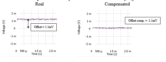
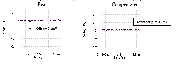
- Offset comp: the offset compensation in Volts for DC coupling.
- Coupling: the input coupling.
| Coupling | Description |
| AC | AC coupling with signal ground connected to the analyzer hardware ground and a 0.35 Hz first order high pass filter. |
| DC | DC coupling with signal ground connected to the analyzer hardware ground. It is advisable to use the DC coupling when analyzing very low frequencies (< 10 Hz frequency range). |
| ICP | AC coupling with ICP current source (nominal 4 mA). Signal ground is connected to the analyzer hardware ground. |
| AC floating 40V |
AC coupling with signal ground floating. This position is used to avoid ground loop problems (absolute input voltage values are 40V). |
| DC floating 40V |
DC coupling with signal ground floating. This position is used to avoid ground loop problems. |
| ICP TEDS | AC coupling with ICP current source (nominal 4 mA). Signal ground is connected to the analyzer hardware ground. This coupling allows inverted current for TEDS detection. |
- Gauge type: Full, Half or Quarter bridge mount. The completion resistors are include in the X-Pod
Hidden/fixed: fixed if the input type is standard/bridge.
- Bridge completion resistor: 120 or 350 Ohms for quarter bridge mount
Hidden/fixed: fixed if the input type is standard/bridge.
- Bridge gain: 10 or 100 depending on the required precision and range
Hidden/fixed: fixed if the input type is standard/bridge.
- Bridge offset comp: Can be used for manual balance of the bridge
Hidden/fixed: fixed if the input type is standard/bridge.
- Enable auto-zero: authorizes the automatic balance on this input or not
Hidden/fixed: fixed if the input type is standard/bridge.
- Input filter: filter to be used for filtering the source before analysis. The Filters that are not compatible with the TDA range cannot be selected (see the Filter builder chapter).
- Enable auto-range: On / Off. "On" allows the auto-range to change the range peak of this input. "Off" will set the input range unchanged.
DC input
Contains all the settings related to the DC input x (optional) such as transducer type, sensitivity. Parametric inputs sampled at Low freq (16 bits for hardware V1 or 24 bits) that provide accurate and stable DC measurement.
Each DC input (#1 to 32#) can be configured for dynamic or parametric measurement. Activating an input from the Inputs list or the DC list, will make the input operate respectively with dynamic or parametric sampling, conditioning and analyses.
Settings for parametric inputs
- Label: the name of this DC input (by default DC input n, with 1 <= n <= 8). The label of each DC input is used in the result name and in all connection tools.
- Transducer: the transducer connected to this DC input. Selecting a transducer will automatically modify the sensitivity.
- Physical qty.: the physical quantity applied to this DC input. It modifies the sensitivity and range peak units if necessary.
Hidden/fixed: fixed if a transducer is selected for this DC input.
- Sensitivity: transducer sensitivity. Changing it updates the range peak.
- Range pk.: the maximum input level for this channel, from 156mV up to 10V. For a sensibility of 2 V/m/s2 those values will be divided by 2 (0.078 m/s2 and 5 m/s2). This setting can be displayed in dB.
- External gain: This enables the analyzer to take into account an external attenuation or amplification: for example if there is an external gain of 3dB, you can set the value of this setting to 3dB to retrieve the genuine amplitude of the signal. This setting can be displayed in dB.
- Polarity: The polarity applied to the signal. If the value is "inverted", positive and negative values are inverted. For example, if the signal value is 4 Volts with "Normal" polarity, it will be -4 Volts with "Inverted" polarity.
| Polarity | Description |
| Normal | Normal polarity |
| Inverted | Positive and negative values are inverted |
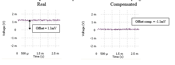
- Offset comp.: the offset compensation in Volts.
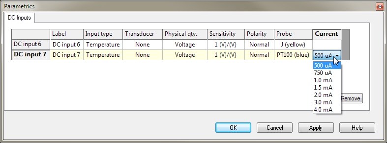
- Probe: Define the type of temperature probe connected on the XPod:
- Thermocouple : J, K, T, N, E
- RTD: PT100, PT1000, PT100 3 wires
For each type of probe the Temperature range is shown in the "Range" setting.
While using RTDs, the applied current can be selected
Hidden/fixed: Hidden if the input type is standard.
- Enable auto-range: On / Off. It allows the auto-range to change the range pk of this DC input.
- Tach: On / Off. Used to activate a tachometer with an RPM level proportional to the DC level
- Rotation: Depending on the way you look at a measured shaft or on the convention you are using, the shaft may be considered as rotating clock wise or counter clock wise. This has noticeable impact on the phase of spectra and orders.
See tachometers § for more details.
Hidden/fixed: Hidden if Tach is Off.
- Average size: defines the average number used to compute the average speed. Revolution number n average speed is: avrg_speed[n-1] + (inst_speed[n-1] - avrg_speed[n-1]) / avrg_size.
Hidden/fixed: Hidden if Tach is Off.
- Max speed: defines the highest measured angular speed. speed higher than Max speed are rejected. By default Max speed is expressed in RPM.
The Max speed setting is also used:
- to specify the limit of Y axis of the RPM profile result
- to compute the limit of the maximum order of the SOA plug-in analyzer.
Hidden/fixed: Hidden if Tach is Off.
CAN Bus
These sub-module contains all the settings related to the parametrics CAN inputs (optional) such as data type, parameters and sensitivity read from CAN interface. The CAN interface handle up to 24 different parameters.
- Label: defines the name of this CAN input (by default CAN input n, with 1 <= n <= 24). The label of each CAN input is used in the result name and in all connection tools.
- Message ID: defines the ID of the message which contains the parameter
- Message NAME: defines the ID of the message which contains the parameter
- First bit position: defines the 1st position of the bit that contains the parameter
- Data length: defines the length of the data which contains the parameter
- Data Format: defines the format of the parameter if this is a "Signed Integer" or "Unsigned Integer"
- Byte order: defines the order of the byte to decode the parameter. This is either "Little endian (Intel)" or "Big endian (Motorola)"
- Physical qty.: defines the physical quantity of the reade value of parameter used to convert to NVGate data.
- Unit.: the Unit of the read value of parameter used to convert to NVGate data
- Scaling factor (LSB): define the scale factor conversion of the parameter to convert to NVGate data
- Offset: defines the offset compensation
Example:
Reading active gear:
Physical quantity: No Magnitude, Unit = No Unit,
Scaling factor (LSB) = 1, Offset = 0
Read Data = 2
NVGate value is: Read Data * Scaling factor (LSB) + Offset
NVGate value is: 2
Reading Acceleration in "g"
Physical quantity acceleration, Unit = Gravity (same as NVGate user Preferences)
Scaling factor (LSB) = 0.01, Offset = 0
Read Data = 1254
NVGate value is: Read Data * Scaling factor (LSB) + Offset
NVGate value is: 12.54g
- Max Value: defines the maximum value allowed for the parameter. This read only setting is automatically computed according to other setting parameters.
- Min Value: defines the minimum value allowed for the parameter. This read only setting is automatically computed according to other setting parameters.
- Tach: On / Off. Used to activate a digital tach whose source is this external sync.
- Rotation: Depending on the way you look at a measured shaft or on the convention you are using, the shaft may be considered as rotating clock wise or counter clock wise. This has noticeable impact on the phase of spectra and orders.
See Tachometers § for more details.
Hidden/fixed: Hidden if Tach is Off.
- Average size: defines the average number used to compute the average speed. Revolution number n average speed is: avrg_speed[n-1] + (inst_speed[n-1] - avrg_speed[n-1]) / avrg_size.
Hidden/fixed: Hidden if Tach is Off.
- Max speed: defines the highest measured angular speed. All revolutions with a speed higher than Max speed are rejected. By default Max speed is expressed in RPM.
The Max speed setting is also used:
- to specify the limit of Y axis of the RPM profile result
- to compute the limit of the maximum order of the SOA plug-in analyzer.
Hidden/fixed: Hidden if Tach is Off.
- Min speed: defines the lowest measured angular speed. All revolutions with a speed lower than Min speed are forced to 0 RPM. By default Min speed is expressed in RPM. The user can enter any value between Max speed / 1000 and Max speed. The max Min speed and min Min speed are defined according to the Max speed and Speed ratio.
Hidden/fixed: Hidden if Tach is Off.
Aux. DC inputs<ref>Optional, depends on hardware options.</ref>
Parametric inputs sampled at Low freq (16 bits) that provide accurate and stable DC measurement.
Contains all the settings related to the DC located on the "aux" part input
See "DC Inputs" for setting details.
External Syncs
Externals syncs are high speed levels comparator that provides accurate events date for the tachs and trigger. External sync is sampled at 64 tim the Front-end sampling frequency in order to achieve higher precision in delay or phase measurements.
For external sync or tach signals whose frequencies overload the inputs sampling rate, an internal hardware divider is available in order to lower signal frequency. The upper frequency of the external sync must be lower than 64 times the Front-end frequency range. At input frequencies greater than 300 kHz, sensitivity can be decreased due to the electronic circuitry.
In any case the maximum frequency of a signal on an Ext Sync (before any pre-divider has been applied) is 375 kHz.
- Label: the name of this External Sync. (by default Ext. sync. n, with 1 <= n <= 2). The label of each External Sync is used in the result name and in all connection tools.
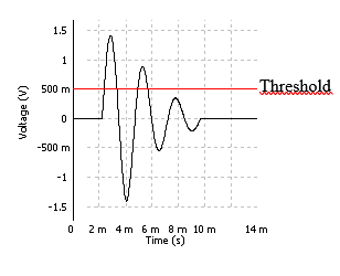
- Threshold: the detection level.
- Slope: the slope associated with the threshold that defines the trigger detection.
| Slope | Description |
| Rise | The threshold is reached on rising edge of the External sync. signal |
| Fall | The threshold is reached on falling edge of the External sync. signal |
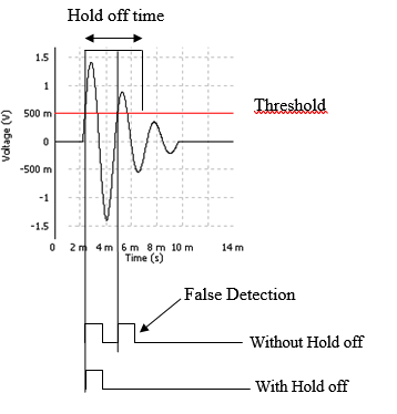
- Hold off: defines the minimum time (expressed in seconds) between two pulses. If a pulse is detected before this time has expired since the last valid pulse then the new pulse is rejected. The user can enter any value between 0 and 36000s.
- Hystersis: defines the hystersis around the threshold. The value can be adjusted between 0 and the full scale of the input signal (depending on the input range).
- If Slope is set to RISE, the input signal must go below Threshold - Hystersis before a new pulse can be detected.
- If Slope is set to FALL, the input signal must go above Threshold + Hystersis before a new pulse can be detected. This setting is used to reject false pulse detection following, for example, a transition of the input signal. This setting can be displayed in dB.
- Pre-'divider': Hardware pre-divider is available after the edge detector and is used to reduce the frequency of the signal to be measured. When the tach is enabled, the measured speed take into account the pre-divider setting when displaying the true RPM value. The user can enter any integer value between 1 and 255. If tach is ’On’ this setting is linked to the ’pulse/rev’ setting.
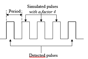
- Post'-mutiplier:' selection of the multiplier factor. It allows to generate an ’ExtSync’ signal which the pulse frequency is multiplied by the selected factor. The user can enter any integer value between 1 and 50. This is particularly used with slow time base as GPS or standard clock.
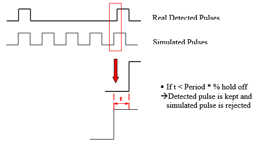
- Multiplier Hold off: defines the maximum time (expressed in percentage of the last period measured after multiplication) between a detected pulse and a simulated pulse. If a simulated pulse is detected before this time has expired since the detected pulse then this pulse is not added. By this way, the simulated signal is synchronize with the input signal. The user can enter any value between 1% and 99%.
- Physical qty.: the physical quantity applied to this External sync. It modifies the sensitivity and range peak units if necessary.
- Sensitivity: the sensitivity of the transducer. Changing it updates the range peak.
- Range pk.: the maximum input level for this channel, from 300mV up to 40V. For a sensibility of 2 V/m/s2 those values will be divided by 2 (0.015 m/s2 and 20 m/s2) and for a gain of 0.1 those values will be multiplied by 10 (3 V and 400V). This setting can be displayed in dB.
- External 'gain': this setting can be displayed in dB. This allows the analyzer to offset an external gain: for example if there is an external gain of 3dB, the value may be set to 3dB to retrieve the genuine amplitude of the signal.
- Offset comp.: the offset compensation in Volts.
- Coupling: the coupling of this external sync.
This article compare the difference beetween coupling AC Vs DC for the tachometer phase.
| Coupling | Description |
| AC | AC coupling with signal ground connected to the analyzer hardware ground and a 0.35 Hz high pass filter. |
| DC | DC coupling with signal ground connected to the analyzer hardware ground. It is advisable to use the DC coupling when analyzing very low frequency (< 10 Hz frequency range). |
- Mode: This setting allows selecting available signal generated by the Ext. synch input to be used by the NVGate analysis components.
| Mode | Description |
| Trigger | The Input generates events only. It can be used as trigger, start and stop of plug-in analyzers and be recorded. Recorded event occurs as 0/1 V signals. Note that the trigger event remains available on any mode. |
| Tach | The input generates a tach signal (RPM and revolution phases) in addition to the events. See Tach § for details |
| Torsional | The input generates the instantaneous velocity measured with the F. to V converter<ref> Optional.</ref> from a pulses train. The torsional signal is considered as a dynamic input. It appears as Tors # in the inputs list (# being the Ext sync number) |
| Torsional + Tach | Same as above plus the tach signal is also available. The revolution phase correspond:
|
| Sampling | The detected pulses on the inputs will be used to synchronize the SOA re-sampling algorithm. The number of pulse/rev is f free and may be different from the SAO resolution. |
| Sampling + Tors | Combine the sampling and the Torsional modes. Both angular re-sampling and instantaneous velocity are provided by the input |
| Sampling + Tach | Combine the sampling and the Tachometer modes. Both angular re-sampling and RPM measurement are provided by the input |
| Sampling + tach + tors | Combine the sampling, the Tachometer and the Torsional modes. Angular re-sampling, Tachometer speed and instantaneous velocity are provided by the input |
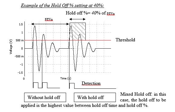
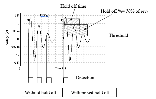
- Hold off (% period): defines the minimum time (expressed in % of the last valid tach period) between 2 tach pulses used to measure RPM.
If a pulse is detected before this time has expired since the last valid pulse then the new pulse is rejected. This is used to reject angular speed variations that are too large. This minimum time is in fact the maximum between the Hold off setting value and the value computed using the last tach period length and the Hold off (% period) setting value.
Hidden/fixed: Hidden if Mode is Trigger or Torsional.
- Pulse / rev: the number of pulses per revolution. The user can enter an integer value between 1 and 4092. For a non-integer number of pulses per revolution the user must use a virtual tach.
Hidden/fixed: Hidden if Mode is Trigger.
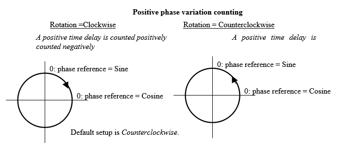
- Rotation: This setting defines the way the phase variation is counted: clockwise or counter-clockwise for each tachometer.
The rotation side is managed independently for each tachometer (Ext. sync, input, D, combined and fractional).
- Average size: defines the average number used to compute the average speed. Revolution number n average speed is: avrg_speed[n-1] + (inst_speed[n-1] - avrg_speed[n-1]) / avrg_size.
Hidden/fixed: Hidden if Mode is Trigger.
- Max speed: defines the highest measured angular speed. All revolutions with a speed higher than Max speed are rejected. By default Max speed is expressed in RPM. The limit of Max speed depends on the sampling frequency of the input, on the pulse/rev and on the hold off. If the Max speed value is modified, the Min speed is automatically adjusted according to a speed ratio (MinSpeed = MaxSpeed / SpeedRatio). The Speed Ratio value is not able to be modified.
The Max speed setting is also used:
- to specify the limit of Y axis of the RPM profile result
- to compute the limit of the maximum order of the SOA plug-in analyzer.
Hidden/fixed: Hidden if Mode is Trigger.
- Min speed: defines the lowest measured angular speed. All revolutions with a speed lower than Min speed are forced to 0 RPM. By default Min speed is expressed in RPM. The user can enter any value between Max speed / 1000 and Max speed. The max Min speed and min Min speed are defined according to the Max speed and Speed ratio.
Hidden/fixed: Hidden if Mode is Trigger.
- Missing teeth: This setting indicates the number of possible consecutive missing teeth (no pulses). In such case depending on the active mode:
- Torsional: the system interpolates the missing pulses intervals in order to maintain the instantaneous speed at a continuous level during the missing pulses.
OROS torsional function is able to manage fractional pulses. It offers to achieve torsional measurement on the field in a simple and easy way.
The empty area (missing teeth) length at the piano tape junction must be included between 1 and 3 teeth. The number of missing teeth must be set to the exact number of missing teeth: In this example: 2.
Note: the total number of teeth includes the missing teeth.
Attention: The time lap of the first missing pulse must be longer than twice the time lap of the previous pulse interval
It is recommended to set the instrumentation in order to limit the number of missing pulse below 3s: Indeed long interval without pulses will lead to a strong order 1 artefact in the instantaneous speed signal due to interpolation of sample. Remaining below 3 missing pulse provide correct measurements
- Tach: the system uses the missing teeth occurrence as the phase reference.
Hidden/fixed: Hidden if Mode is Trigger
- Input filter: Select the filter to apply on the instantaneous angular velocity signal computed by the torsional converter. The applied bandwidth is the front-end one.
Hidden/fixed: Hidden if Mode is Trigger or Tach
Aux. External Syncs
Contains all the settings related to the auxiliary External sync. x such as threshold, slope, tach.
See External Syncs for. Aux. External Syncs setting details.
Output settings
Used to control general output behavior. i.e. the signal generated on Out 1 &2 and Aux. Out 1 to 4.
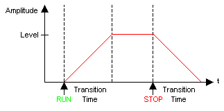
- Transition time: The value of this setting is the time it takes for the output to go from 0 to activated level and the time it takes for the output to go from the activated level to 0 when deactivated. This transition time is applied only if the Output x/transition control value is "On"
- Mute 'all': On / Off: When "On", all the outputs are set to zero. The value of this setting is automatically set is "On" when the Emergency Stop setting from the same sub-module is pushed.
'Emergency 'Stop: Automatically mutes all the outputs when pushed. Use the Mute all setting from the same sub-module to make the outputs work again.
Outputs
Contains all the settings related to the output x.
- Label: the name of this Output (by default Output n, with 1 <= n <= 2). The label of each output is used in the result name and in all connection tools.
- Source: the input signal of the output (NONE by default). The input signal can be any dynamic input of the Front-end (in the On-line mode) or any signal generated by the output signals resource (in the On-line mode) or any track of the Player (recorded from inputs).
- Applied 'filter': the filter applied to this output. The list of filters applicable to the outputs is defined in the Filter module, by choosing Apply to= All.
- Clipping: the amplitude limitation of the output signal (from 1 mV to 10 V).
- Gain: This setting can be displayed in dB. It is the gain applied to the output signal.
- Impedance:
| Impedance | Description |
| GND | The output is connected to the ground. |
| 50 Ohms | The output impedance is equal to 50 Ohms. |
| 600 Ohms<ref>Only available for OR38 & OR36. For phone lines connections use.</ref> | The output impedance is equal to 600 Ohms. |
- Synchronization:
| Synchronization | Description |
| Free run | The output delivers a signal as soon as there is a source connected. |
| Linked to run | The output is activated only after the first run action. |
- Transition control: On / Off. If the value of this setting is "On" the Output settings/transition time is applied when this output is activated or disabled.
Aux. Output
Contains all the settings related to the auxiliary output.
See Outputs § for Aux. Output setting details.
<references/>
