Difference between revisions of "NVGate Output Signals"
| (32 intermediate revisions by 3 users not shown) | |||
| Line 1: | Line 1: | ||
[[category:NVGate]] | |||
This module generates multiple signals such as fixed sinus, random noises, and swept sinus. You can have up to 6 outputs channels with OROS analyzers. | |||
==Connect== | |||
<Youtube>https://youtu.be/cXtX7NVTtmg?t=17</Youtube> | |||
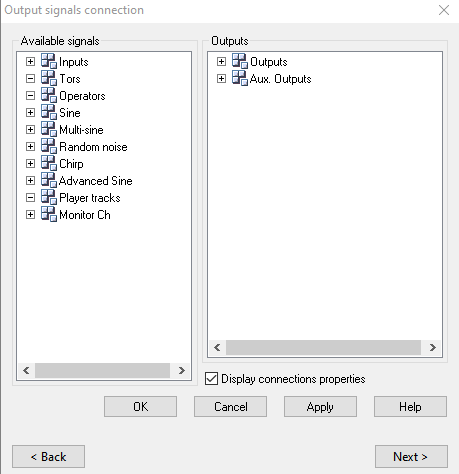
The left button (''signals'') allows selecting the signal type from the list and connecting it to the available outputs (1 to 6) .The | |||
[[Image:Reports_Tools_Ribbons_344.png|250px|none]] | |||
On the tab [[NVGate_Ribbons:_Acquisition_Tab|acquisition]], Output can generate a signal on the front-end outputs (generators) | |||
The left button (''signals'') allows selecting the signal type from the list and connecting it to the available outputs (1 to 6) .The other buttons open the signal settings and manage the generators activity. | |||
*[[Image:Reports_Tools_Ribbons_345.png|Reports_Tools_Ribbons_345.png]] ''Signals:'' Shows the list of available signals and let the users connect it to the outputs. You can easily connect signal with a "drag and drop" on the windows below. | *[[Image:Reports_Tools_Ribbons_345.png|Reports_Tools_Ribbons_345.png]] ''Signals:'' Shows the list of available signals and let the users connect it to the outputs. You can easily connect signal with a "drag and drop" on the windows below. | ||
| Line 12: | Line 16: | ||
==Settings== | ==Settings== | ||
===Output | ===Output general settings=== | ||
[[Image:Reports_Tools_Ribbons_351.png]] Outputs settings: Manages the generated signal settling, (Mute, transition time). It is also available on ASB front end. | [[Image:Reports_Tools_Ribbons_351.png]] Outputs settings: Manages the generated signal settling, (Mute, transition time). It is also available on ASB front end. | ||
[[File:out4.png|framed|right]] | [[File:out4.png|framed|right]] | ||
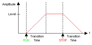
| Line 24: | Line 28: | ||
'''Emergency ''''''Stop''': Automatically mutes all the outputs when pushed. Use the ''Mute all ''setting from the same sub-module to make the outputs work again. | '''Emergency ''''''Stop''': Automatically mutes all the outputs when pushed. Use the ''Mute all ''setting from the same sub-module to make the outputs work again. | ||
===Output | ===Output chanel settings=== | ||
Available on ASB/ front end/Ouput.<br> | Available on ASB/ front end/Ouput.<br> | ||
[[image:out5.png|framed|right]] | [[image:out5.png|framed|right]] | ||
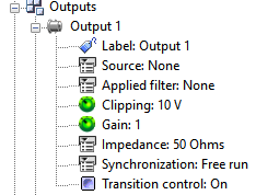
* '''Label''': the name of this Output (by default Output n, with 1 <nowiki><</nowiki>= n <nowiki><</nowiki>= 2). The label of each output is used in the result name and in all connection tools. | * '''Label''': the name of this Output (by default Output n, with 1 <nowiki><</nowiki>= n <nowiki><</nowiki>= 2). The label of each output is used in the result name and in all connection tools. | ||
* '''Source''': the input signal of the output (NONE by default). The input signal can be any dynamic input of the Front-end (in the On-line mode) or any signal generated by the output signals resource (in the On-line mode) or any track of the Player (recorded from inputs). | * '''Source''': the input signal of the output (NONE by default). The input signal can be any dynamic input of the Front-end (in the On-line mode) or any signal generated by the output signals resource (in the On-line mode) or any track of the Player (recorded from inputs). | ||
* '''Applied ''''''filter''': the filter applied to this output. The list of filters applicable to the outputs is defined in the Filter module, by choosing Apply to= All. | * '''Applied ''''''filter''': the filter applied to this output. The list of filters applicable to the outputs is defined in the Filter module, by choosing Apply to = All. | ||
* '''Clipping''': the amplitude limitation of the output signal (from 1 mV to 10 V). | * '''Clipping''': the amplitude limitation of the output signal (from 1 mV to 10 V). | ||
* '''Gain''': This setting can be displayed in dB. It is the gain applied to the output signal. | * '''Gain''': This setting can be displayed in dB. It is the gain applied to the output signal. | ||
* '''Impedance''': | * '''Impedance''': | ||
{|border="2" cellspacing="0" cellpadding="4" width="77%" align="center" | {|class="wikitable" style="background:white" border="2" cellspacing="0" cellpadding="4" width="77%" align="center" | ||
|'''Impedance''' | |'''Impedance''' | ||
|'''Description''' | |'''Description''' | ||
| Line 54: | Line 58: | ||
* '''Synchronization''': | * '''Synchronization''': | ||
{|border="2" cellspacing="0" cellpadding="4" width="92%" align="center" | {|class="wikitable" style="background:white" border="2" cellspacing="0" cellpadding="4" width="92%" align="center" | ||
|'''Synchronization''' | |'''Synchronization''' | ||
|'''Description''' | |'''Description''' | ||
| Line 74: | Line 78: | ||
* [[Image:Reports_Tools_Ribbons_346.png]] ''Sine:'' Opens the pure sine properties dialog for adjustment. | * [[Image:Reports_Tools_Ribbons_346.png]] ''Sine:'' Opens the pure sine properties dialog for adjustment. | ||
Used to generate and configure up to 6 fixed sinus. A sinusoidal signal is generated with the frequency specified in the sine '''Frequency''' field. The frequency corresponds to one of the analysis bands. This type of signal is used for measuring the amount of distortion in a system | Used to generate and configure up to 6 fixed sinus. A sinusoidal signal is generated with the frequency specified in the sine '''Frequency''' field. The frequency corresponds to one of the analysis bands. This type of signal is used for measuring the amount of distortion in a system for example. The amplitude of the signal can be changed using the '''Level''' settings. | ||
[[Image:Resources_output_02.png|framed|none]] | [[Image:Resources_output_02.png|framed|none]] | ||
| Line 106: | Line 110: | ||
* '''Phase''': Computational mode of the original sinusoid phases. | * '''Phase''': Computational mode of the original sinusoid phases. | ||
{|border="2" cellspacing="0" cellpadding="4" width="100%" align="center" | {|class="wikitable" style="background:white" border="2" cellspacing="0" cellpadding="4" width="100%" align="center" | ||
|'''Phase''' | |'''Phase''' | ||
|'''Description''' | |'''Description''' | ||
| Line 131: | Line 135: | ||
'''Burst setting''' in Multisine generators will shorten time during which output signal is active despite signal block being of the same length. | '''Burst setting''' in Multisine generators will shorten the time during which the output signal is active despite the signal block being of the same length. | ||
All bandwidth frequencies are present in each burst but may not be complete cycles as block period is truncated. Two bursts being identical (respectively fixed or random phase) they are 100% correlated. Two | All bandwidth frequencies are present in each burst but may not be complete cycles as block period is truncated. Two bursts being identical (respectively fixed or random phase) they are 100% correlated. Two random bursts from two separate generators will not be correlated signals. | ||
===Random noise=== | ===Random noise=== | ||
| Line 149: | Line 153: | ||
* '''Upper frequency''': the upper frequency of the Random noise frequency range. Its maximum value is SF / 2.56, where SF is the sampling frequency. | * '''Upper frequency''': the upper frequency of the Random noise frequency range. Its maximum value is SF / 2.56, where SF is the sampling frequency. | ||
* '''RMS level''': the Random noise RMS level. This setting can be displayed in dB. | * '''RMS level''': the Random noise RMS level. This setting can be displayed in dB. | ||
* '''Period''': The period selected for the Random noise. It used to define a Random Block. Its maximum value is | * '''Period''': The period selected for the Random noise. It used to define a Random Block. Its maximum value is 100s. | ||
* '''Burst''': This setting lets the user specify the percentage of non-null signal in a random block. | * '''Burst''': This setting lets the user specify the percentage of non-null signal in a random block. | ||
'''Exemple''' with: burst: 60% - period: 100ms : | |||
[[Image:Resources_output_09.png|framed|none]] | [[Image:Resources_output_09.png|framed|none]] | ||
| Line 156: | Line 162: | ||
* '''Type''': | * '''Type''': | ||
{|border="2" cellspacing="0" cellpadding="4" width="92%" align="center" | {|class="wikitable" style="background:white" border="2" cellspacing="0" cellpadding="4" width="92%" align="center" | ||
|'''Type''' | |'''Type''' | ||
|'''Description''' | |'''Description''' | ||
| Line 184: | Line 190: | ||
* '''Size''': This setting specifies the number of samples required for the generator to go from the lower frequency to the upper one. | * '''Size''': This setting specifies the number of samples required for the generator to go from the lower frequency to the upper one. | ||
{|border="2" cellspacing="0" cellpadding="4" width="31%" align="center" | {|class="wikitable" style="background:white" border="2" cellspacing="0" cellpadding="4" width="31%" align="center" | ||
|align = "center"|'''Block size''' | |align = "center"|'''Block size''' | ||
|align = "center"|'''FFT lines number''' | |align = "center"|'''FFT lines number''' | ||
| Line 241: | Line 247: | ||
* '''Mode''': | * '''Mode''': | ||
{|border="2" cellspacing="0" cellpadding="4" width="91%" align="center" | {|class="wikitable" style="background:white" border="2" cellspacing="0" cellpadding="4" width="91%" align="center" | ||
|'''Mode''' | |'''Mode''' | ||
|'''Description''' | |'''Description''' | ||
| Line 269: | Line 275: | ||
If you change the amplitude or the frequency of the generated signal, there will be a stabilization time, and you will have to generate an event when the signal is stabilized. | If you change the amplitude or the frequency of the generated signal, there will be a stabilization time, and you will have to generate an event when the signal is stabilized. | ||
In | In these 3 modes, each time the generator stops on a frequency; | ||
1. | 1. At the beginning (amplitude increase until the first frequency), | ||
2. | 2. At a new step (at the end of stabilization time), or in <nowiki>’</nowiki>pure tone<nowiki>’</nowiki> or <nowiki>’</nowiki>swept sine<nowiki>’</nowiki> pause mode when it reaches the target frequency; the generator sends a stabilized event, after being stabilized (amplitude and frequency). | ||
3. In <nowiki>’</nowiki>Free run<nowiki>’</nowiki>, if the generator is already stabilized at the run event, then a stabilized event is generated at this moment. | 3. In <nowiki>’</nowiki>Free run<nowiki>’</nowiki>, if the generator is already stabilized at the run event, then a stabilized event is generated at this moment. | ||
| Line 281: | Line 287: | ||
:''Hidden/fixed:'' | :''Hidden/fixed:'' | ||
{|border="2" cellspacing="0" cellpadding="4" width="70%" align="center" | {|class="wikitable" style="background:white" border="2" cellspacing="0" cellpadding="4" width="70%" align="center" | ||
|'''Mode''' | |'''Mode''' | ||
|'''Sweep''' | |'''Sweep''' | ||
| Line 295: | Line 301: | ||
|}<br clear="all"> | |}<br clear="all"> | ||
* '''Pause''': On / Off. When Pause is active, the frequency sweeping is halted | * '''Pause''': On / Off. When Pause is active, the frequency sweeping is halted when there is only one frequency generated. This frequency is now called "Target frequency". You can modify this frequency value to another target so the frequency will sweep to the new target. | ||
[[Image:Resources_output_16.png|framed|none]] | [[Image:Resources_output_16.png|framed|none]] | ||
| Line 301: | Line 307: | ||
''Hidden/fixed:'' | ''Hidden/fixed:'' | ||
{|border="2" cellspacing="0" cellpadding="4" width="70%" align="center" | {|class="wikitable" style="background:white" border="2" cellspacing="0" cellpadding="4" width="70%" align="center" | ||
|'''Mode''' | |'''Mode''' | ||
|'''Sweep''' | |'''Sweep''' | ||
| Line 320: | Line 326: | ||
''Hidden/fixed:'' | ''Hidden/fixed:'' | ||
{|border="2" cellspacing="0" cellpadding="4" width="70%" align="center" | {|class="wikitable" style="background:white" border="2" cellspacing="0" cellpadding="4" width="70%" align="center" | ||
|'''Mode''' | |'''Mode''' | ||
|'''Sweep''' | |'''Sweep''' | ||
| Line 338: | Line 344: | ||
''Hidden/fixed:'' | ''Hidden/fixed:'' | ||
{|border="2" cellspacing="0" cellpadding="4" width="70%" align="center" | {|class="wikitable" style="background:white" border="2" cellspacing="0" cellpadding="4" width="70%" align="center" | ||
|'''Mode''' | |'''Mode''' | ||
|'''Sweep''' | |'''Sweep''' | ||
| Line 356: | Line 362: | ||
''Hidden/fixed: '' | ''Hidden/fixed: '' | ||
{|border="2" cellspacing="0" cellpadding="4" width="73%" align="center" | {|class="wikitable" style="background:white" border="2" cellspacing="0" cellpadding="4" width="73%" align="center" | ||
| '''Mode''' | | '''Mode''' | ||
|'''Sweep''' | |'''Sweep''' | ||
| Line 372: | Line 378: | ||
* '''Sweep variation''': Two different types of sweep are available: a linear sweeping or a logarithmic sweep: | * '''Sweep variation''': Two different types of sweep are available: a linear sweeping or a logarithmic sweep: | ||
{|border="2" cellspacing="0" cellpadding="4" width="74%" align="center" | {|class="wikitable" style="background:white" border="2" cellspacing="0" cellpadding="4" width="74%" align="center" | ||
|'''Sweep variation''' | |'''Sweep variation''' | ||
|'''Description''' | |'''Description''' | ||
| Line 378: | Line 384: | ||
|- | |- | ||
|Lin | |Lin | ||
|The Sweep speed is constant | |The Sweep speed is constant. | ||
|- | |- | ||
|Log | |Log | ||
|The Sweep speed increases exponentially when the frequency increase is linear | |The Sweep speed increases exponentially when the frequency increase is linear. | ||
|}<br clear="all"> | |}<br clear="all"> | ||
| Line 388: | Line 394: | ||
''Hidden/fixed:'' | ''Hidden/fixed:'' | ||
{|border="2" cellspacing="0" cellpadding="4" width="73%" align="center" | {|class="wikitable" style="background:white" border="2" cellspacing="0" cellpadding="4" width="73%" align="center" | ||
|'''Mode''' | |'''Mode''' | ||
|'''Sweep''' | |'''Sweep''' | ||
| Line 402: | Line 408: | ||
|}<br clear="all"> | |}<br clear="all"> | ||
* '''Sweep speed''': It is expressed in Hz/s in a linear sweep variation, and in dec/s in a logarithmic sweep variation. | * '''Sweep speed''': It is expressed in Hz/s in a linear sweep variation, and in dec/s in a logarithmic sweep variation. The unit of the logarithmic sweep speed can be changed to oct/min in the user preferences/physical quantity (select "Sweep speed (logarithmic)" in the physical quantity list). | ||
''Hidden/fixed:'' | ''Hidden/fixed:'' | ||
{|border="2" cellspacing="0" cellpadding="4" width="73%" align="center" | {|class="wikitable" style="background:white" border="2" cellspacing="0" cellpadding="4" width="73%" align="center" | ||
|'''Mode''' | |'''Mode''' | ||
|'''Sweep''' | |'''Sweep''' | ||
| Line 423: | Line 429: | ||
[[Image:Resources_output_17.png|framed|none]] | [[Image:Resources_output_17.png|framed|none]] | ||
{|border="2" cellspacing="0" cellpadding="4" width="73%" align="center" | {|class="wikitable" style="background:white" border="2" cellspacing="0" cellpadding="4" width="73%" align="center" | ||
|'''Sweep type''' | |'''Sweep type''' | ||
|'''Description''' | |'''Description''' | ||
| Line 443: | Line 449: | ||
''Hidden/fixed:'' | ''Hidden/fixed:'' | ||
{|border="2" cellspacing="0" cellpadding="4" width="73%" align="center" | {|class="wikitable" style="background:white" border="2" cellspacing="0" cellpadding="4" width="73%" align="center" | ||
|'''Mode''' | |'''Mode''' | ||
|'''Sweep''' | |'''Sweep''' | ||
| Line 463: | Line 469: | ||
''Hidden/fixed:'' | ''Hidden/fixed:'' | ||
{|border="2" cellspacing="0" cellpadding="4" width="73%" align="center" | {|class="wikitable" style="background:white" border="2" cellspacing="0" cellpadding="4" width="73%" align="center" | ||
|'''Mode''' | |'''Mode''' | ||
|'''Sweep''' | |'''Sweep''' | ||
| Line 480: | Line 486: | ||
''Hidden/fixed:'' | ''Hidden/fixed:'' | ||
{|border="2" cellspacing="0" cellpadding="4" width="73%" align="center" | {|class="wikitable" style="background:white" border="2" cellspacing="0" cellpadding="4" width="73%" align="center" | ||
|'''Mode''' | |'''Mode''' | ||
|'''Sweep''' | |'''Sweep''' | ||
| Line 544: | Line 550: | ||
==Listening track== | ==Listening track== | ||
There are 3 ways to listen track: | |||
====Input: listen during measurement==== | ====Input: listen during measurement==== | ||
Back to the roots of vibration analysis: Everybody knows that our ears and brain is the best instrument to feel and interpret vibration signals. This is also why we take so much care in removing these NVH signals from our machines, vehicles and appliances. The audio playback of vibration (or any other) signal allows the user to "listen in" on what your OROS analyzer is "hearing". | Back to the roots of vibration analysis: Everybody knows that our ears and brain is the best instrument to feel and interpret vibration signals. This is also why we take so much care in removing these NVH signals from our machines, vehicles and appliances. The audio playback of vibration (or any other) signal allows the user to "listen in" on what your OROS analyzer is "hearing". | ||
Connect input feature | Connect input feature allows a user to play input channels on an output. This allows the user to listen during measurement with an headphone on the output. | ||
====Monitor channels : Hot Swap | ====Monitor channels : Hot Swap ==== | ||
| Line 556: | Line 563: | ||
The NVGate synopsis is as follows: | The NVGate synopsis is as follows: | ||
[[Image:Release_note_20.png| | [[Image:Release_note_20.png|700px|none]] | ||
To activate it, simply connect one of the monitor ''Channels'' to the desired output from the ''Acquisition/Outputs/Signal'' dialog. | To activate it, simply connect one of the monitor ''Channels'' to the desired output from the ''Acquisition/Outputs/Signal'' dialog. | ||
| Line 562: | Line 569: | ||
[[Image:Release_note_21.png|framed|none]] | [[Image:Release_note_21.png|framed|none]] | ||
Then you can add any front-end input to the monitor channel. The selected input signal will replicate (play) on the output. You can swap | Then you can add any front-end input to the monitor channel. The selected input signal will replicate (play) on the output. You can swap from one input to another at any time including during the run and signal recording. | ||
NB: Remember to switch the output impedance to 600 Ω for better listening quality. | NB: Remember to switch the output impedance to 600 Ω for better listening quality. | ||
====Play-Back on PC speaker==== | ====Play-Back on PC speaker==== | ||
If you need to listen a signal already | If you need to listen a signal already recorded, do not use an output channel. We advice to use the playback on PC speaker defined here: | ||
From any of the previous configurations, the recorded signal | From any of the previous configurations, the recorded signal can be listened to on PC speakers. | ||
[[File:Player_playback.png|none]] | [[File:Player_playback.png|none]] | ||
Click on [[Image:Player_connection_wizard_06.png]] in the active window. The button stops the play back at any time. A mobile cursor (blue) localizes the played back signal part in the signal window. | Click on [[Image:Player_connection_wizard_06.png]] in the active window. The button stops the play back at any time. A mobile cursor (blue) localizes the played back signal part in the signal window. | ||
== | ==Create and play ANY signal== | ||
You can play a signal already | You can play a signal already recorded with an OROS analyzer, or any signal imported into NVgate. | ||
You can put the signal in the player (even in connected mode) allowing the signal to be played on an ouptut channel. | |||
==== | ====Example : playing a triangle signal on analyzer output ==== | ||
• Generate a triangular signal with an application ([https://fr.mathworks.com/?requestedDomain= Matlab],…) or an online site (example: http://onlinetonegenerator.com/);<br> | • Generate a triangular signal with an application ([https://fr.mathworks.com/?requestedDomain= Matlab],…) or an online site (example: http://onlinetonegenerator.com/);<br> | ||
| Line 592: | Line 599: | ||
•If you want to play this signal repeatedly, you must change the "Repeat mode" parameter in "Analyzer Setting Browser": | •If you want to play this signal repeatedly, you must change the "Repeat mode" parameter in "Analyzer Setting Browser": | ||
[[File:player_out2.png|framed|none]] | [[File:player_out2.png|framed|none]] | ||
Latest revision as of 09:37, 6 September 2024
This module generates multiple signals such as fixed sinus, random noises, and swept sinus. You can have up to 6 outputs channels with OROS analyzers.
Connect
On the tab acquisition, Output can generate a signal on the front-end outputs (generators)
The left button (signals) allows selecting the signal type from the list and connecting it to the available outputs (1 to 6) .The other buttons open the signal settings and manage the generators activity.
 Signals: Shows the list of available signals and let the users connect it to the outputs. You can easily connect signal with a "drag and drop" on the windows below.
Settings
Output general settings
![]() Outputs settings: Manages the generated signal settling, (Mute, transition time). It is also available on ASB front end.
Outputs settings: Manages the generated signal settling, (Mute, transition time). It is also available on ASB front end.
Used to control general output behavior. i.e. the signal generated on Out 1 &2 and Aux. Out 1 to 4.
- Transition time: The value of this setting is the time it takes for the output to go from 0 to activated level and the time it takes for the output to go from the activated level to 0 when deactivated. This transition time is applied only if the Output x/transition control value is "On"
- Mute 'all': On / Off: When "On", all the outputs are set to zero. The value of this setting is automatically set is "On" when the Emergency Stop setting from the same sub-module is pushed.
'Emergency 'Stop: Automatically mutes all the outputs when pushed. Use the Mute all setting from the same sub-module to make the outputs work again.
Output chanel settings
Available on ASB/ front end/Ouput.
- Label: the name of this Output (by default Output n, with 1 <= n <= 2). The label of each output is used in the result name and in all connection tools.
- Source: the input signal of the output (NONE by default). The input signal can be any dynamic input of the Front-end (in the On-line mode) or any signal generated by the output signals resource (in the On-line mode) or any track of the Player (recorded from inputs).
- Applied 'filter': the filter applied to this output. The list of filters applicable to the outputs is defined in the Filter module, by choosing Apply to = All.
- Clipping: the amplitude limitation of the output signal (from 1 mV to 10 V).
- Gain: This setting can be displayed in dB. It is the gain applied to the output signal.
- Impedance:
| Impedance | Description |
| GND | The output is connected to the ground. |
| 50 Ohms | The output impedance is equal to 50 Ohms. |
| 600 Ohms<ref>Only available for OR38 & OR36. For phone lines connections use.</ref> | The output impedance is equal to 600 Ohms. |
- Synchronization:
| Synchronization | Description |
| Free run | The output delivers a signal as soon as there is a source connected. |
| Linked to run | The output is activated only after the first run action. |
- Transition control: On / Off. If the value of this setting is "On" the Output settings/transition time is applied when this output is activated or disabled.
Signal available
Sine
Used to generate and configure up to 6 fixed sinus. A sinusoidal signal is generated with the frequency specified in the sine Frequency field. The frequency corresponds to one of the analysis bands. This type of signal is used for measuring the amount of distortion in a system for example. The amplitude of the signal can be changed using the Level settings.
Frequency: sine frequency. Tips: put 0 for DC Volatge generation.
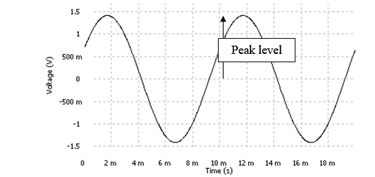
- Peak level: the peak level
- RMS level: sine RMS level. This setting can be displayed in dB.
Note: Amplitude and frequency modifications are applied immediately without any transition.
Multi-sine
![]() : Multi-sine: Opens the Multi-sine properties dialog for adjustment.
: Multi-sine: Opens the Multi-sine properties dialog for adjustment.
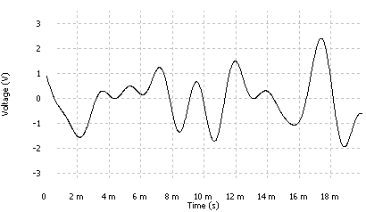
Multisine is computed by adding sine signals whose frequencies are power of two sub-modules of sampling frequency. This means that multisine output block includes all discrete sine waves of FFT spectrum of corresponding block size and resolution. Multisine has the advantage of showing no leakage effect in FFT as all sine waves are exact periods of the trigger block for FFT computation. The most appropriate FFT weighting window to be used is “uniform” window. Multisine generators work on a sample block basis, it means signal blocks are repeated identically over time.
Used to generate and configure up to 2 multi-sines. The multi-sine is computed by adding sine signals whose frequencies are power of two sub-modules of sampling frequency. So with the FFT analyzer, each sine signal can be exactly at an analysis frequency line and there is no leakage due to analysis window. Due to its specific structure, using a rectangular analysis window for FFT analysis on a multi-sine excitation is recommended.
The phase between sine signals can be controlled in order to get a low crest factor or randomized, but with a higher crest factor.
Multi-sine is periodic with a period equal to the opposite of its frequency resolution.
- Lower frequency: the lower frequency of the multi-sine frequency range. Its minimum value is the resolution.
- Upper frequency: the upper frequency of the multi-sine frequency range. Its maximum value is SF / 2.56, where SF is the sampling frequency.
- RMS level: multi-sine RMS level. This setting can be displayed in dB.
- Resolution: the resolution of the multi-sine. Its minimum value is SF / 16384, where SF is the sampling frequency. Its maximum value is SF / 256.
- Phase: Computational mode of the original sinusoid phases.
| Phase | Description |
| Random |
The original phase of each sinusoid is selected randomly after each multi sine deactivation/activation. First activation:
Phase relationship between sine waves is selected at selection of setting and will not change unless “random” setting is changed back and forward. After “random” is selected phase relationship is defined (randomly for the first block) and repeated identically for each signal block of N lines. Phase relationship for all multisine generators will be different as random setting activation is made at different moment in time and applied for different generator objects. Two blocks of multisine random phase of the same generator are 100% correlated.
Two mulitsine random phase generators are not correlated.
|
| Fixed |
Each sinusoid has the same original phase even after multi sine deactivation/activation. Multisine phase relation if fixed and will be the same each time setting “fixed” is selected.
Phase relationship is the same for all multisine generators meaning that signal blocks will be the identical between any multisine generators of the same setting. Multisine fixed phase generators are 100% correlated.
|
Burst setting in Multisine generators will shorten the time during which the output signal is active despite the signal block being of the same length.
All bandwidth frequencies are present in each burst but may not be complete cycles as block period is truncated. Two bursts being identical (respectively fixed or random phase) they are 100% correlated. Two random bursts from two separate generators will not be correlated signals.
Random noise
![]() Random Noise: Opens the Random noise properties dialog for adjustment. Adapted for non linear responses measurement.
Random Noise: Opens the Random noise properties dialog for adjustment. Adapted for non linear responses measurement.
Used to generate and configure up to 2 white or pink random noise types.
Signal block is recalculated each time. All frequencies of generator bandwidth are taken into account with a resolution of Fs/16384 (Fs being front end sampling frequency), this resolution is independent from FFT resolution. Consequently signal content of each FFT trigger block is not the same meaning that signals between two trigger blocks are not correlated. Similarly random noise signal between two separate generators are also not correlated.
Random noise is generated using algorithms that guarantee no short or long-term periodicity.
- Lower frequency: the lower frequency of the Random noise frequency range. Its minimum value is equal to SF / (2.56 * 6400), where SF is the sampling frequency and 6400 + 1 is the resolution.
- Upper frequency: the upper frequency of the Random noise frequency range. Its maximum value is SF / 2.56, where SF is the sampling frequency.
- RMS level: the Random noise RMS level. This setting can be displayed in dB.
- Period: The period selected for the Random noise. It used to define a Random Block. Its maximum value is 100s.
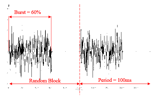
- Burst: This setting lets the user specify the percentage of non-null signal in a random block.
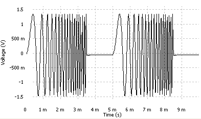
Exemple with: burst: 60% - period: 100ms :
- Type:
| Type | Description |
| White | White noise has the same distribution of power for all frequencies, so there is the same amount of power between 0 and 500 Hz, 500 and 1,000 Hz or 20,000 and 20,500 Hz. |
| Pink | Pink noise has the same distribution of power for each octave, so the power between 0.5 Hz and 1 Hz is the same as between 5,000 Hz and 10,000 Hz. Since power is proportional to amplitude squared, the energy per Hz will decline at higher frequencies at the rate of -10dB/decade. |
Chirp
Chirp means continuous short term variable frequency (1 analysis block), 1 amplitude. Adapted for damping measurement and FFT analysis.
![]() Chirp: Opens the Chirp properties dialog for adjustment.
Chirp: Opens the Chirp properties dialog for adjustment.
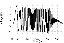
Used to generate and configure up to 6 chirps. A sine signal, of which the frequency varies from Lower Frequency to Upper Frequency, is generated in the delay corresponding to the size of a generator block.
- Lower frequency: the lower frequency of the Random noise frequency range. Its minimum value is equal to SF / (2.56 * 6400), where SF is the sampling frequency and 6400 + 1 is the resolution.
- Upper frequency: the upper frequency of the chirp frequency range. Its maximum value is SF / 2.56, where SF is the sampling frequency.
- RMS level: the chirp RMS level. This setting can be displayed in dB.
- Size: This setting specifies the number of samples required for the generator to go from the lower frequency to the upper one.
| Block size | FFT lines number |
| 256 | 101 |
| 512 | 201 |
| 1024 | 401 |
| 2048 | 801 |
| 4096 | 1601 |
| 8192 | 3201 |
| 16384 | 6401 |
- Burst: This setting lets the user specify the percentage of non-null signal greater than the size of a generator block. For instance, for a burst value of 25% and a block size of 1024, the generator delivers blocks of 256 samples of chirp separated by blocks of 768 null samples.
| Size = 256 Burst = 70 |
Advanced sine
![]() Swept-sine: Opens the Swept-sine properties dialog for adjustment.
Swept-sine: Opens the Swept-sine properties dialog for adjustment.
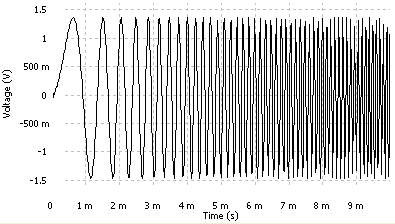
Used to generate and configure up to 6 advanced sines, allowing the user to generate a swept sine, a pure tone, or to sweep step-by-step.
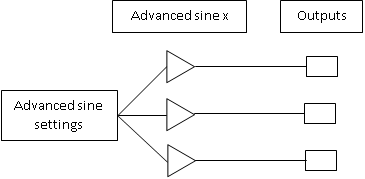
- Gain: Each advanced sine has a gain setting with a 0dB reference that is the value of the Advanced sine settings/ Peak level setting
- Phase offset: All the advanced sine have the same phase reference. This setting is used to set a phase offset between them.
Advanced sine settings
This sub-module contains the settings related to the main advanced sine generator, including the advanced sine mode setting, stabilization time, amplitude variation...
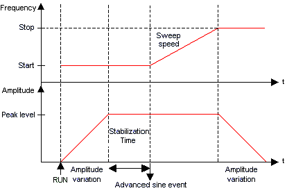
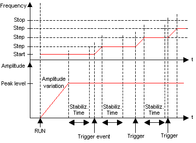
- Mode:
| Mode | Description |
| Sweep: |
The advanced sine performs a continuous sweep of the frequencies between Start Frequency and Stop Frequency |
| Step: |
The advanced sine performs a sweep of the frequencies between Start Frequency and Stop Frequency, it stops at each step, waits during stabilization time, and waits for the new step event before going on. |
| Pure tone: |
The advanced sine generates a pure sine with the frequency of the Advanced sine settings/ Target Frequency value |
- Synchronization: "linked to run" or "Free run". The Advanced sine generator will not be stopped by a stop event, if the setting is on ’Free run’. The default value is ’Linked to run’.
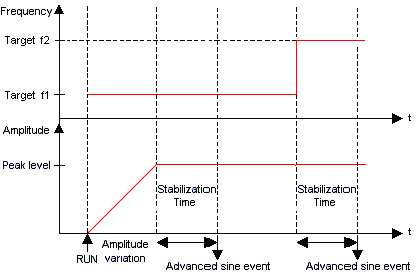
If you change the amplitude or the frequency of the generated signal, there will be a stabilization time, and you will have to generate an event when the signal is stabilized.
In these 3 modes, each time the generator stops on a frequency;
1. At the beginning (amplitude increase until the first frequency),
2. At a new step (at the end of stabilization time), or in ’pure tone’ or ’swept sine’ pause mode when it reaches the target frequency; the generator sends a stabilized event, after being stabilized (amplitude and frequency).
3. In ’Free run’, if the generator is already stabilized at the run event, then a stabilized event is generated at this moment.
If the output is on ’Advanced sine’ source, the setting of ’Synchronization’ of the advanced sine will recopied to the ’synchronization’ of the output (which one become fixed).
- Hidden/fixed:
| Mode | Sweep | Step | Pure tone |
| Synchronization | Fixed to ’Linked to run’ | Visible | Visible |
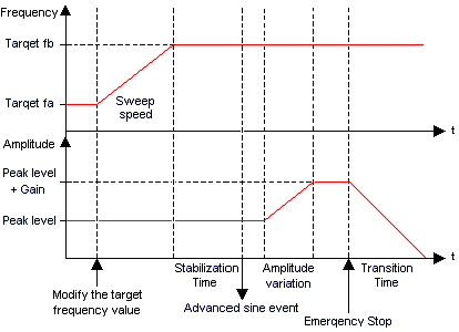
- Pause: On / Off. When Pause is active, the frequency sweeping is halted when there is only one frequency generated. This frequency is now called "Target frequency". You can modify this frequency value to another target so the frequency will sweep to the new target.
Hidden/fixed:
| Mode | Sweep | Step | Pure tone |
| Pause | visible | hidden | hidden |
- Peak level: the advanced sine peak level (between 0 and 10 V).
- Start frequency: The start frequency of the sweep.
Hidden/fixed:
| Mode | Sweep | Step | Pure tone |
| Start frequency | visible | visible | hidden |
- Stop frequency: The stop frequency of the sweep.
Hidden/fixed:
| Mode | Sweep | Step | Pure tone |
| Stop frequency | visible | visible | hidden |
- Target frequency: The value of this setting is the frequency currently generated when the value of the Pause setting is "On" or if the Mode is set to "Pure Tone"
Hidden/fixed:
| Mode | Sweep | Step | Pure tone |
| Target frequency | visible if Pause = On | visible if Pause = On | visible |
- Sweep variation: Two different types of sweep are available: a linear sweeping or a logarithmic sweep:
| Sweep variation | Description |
| Lin | The Sweep speed is constant. |
| Log | The Sweep speed increases exponentially when the frequency increase is linear. |
Hidden/fixed:
| Mode | Sweep | Step | Pure tone |
| Sweep variation | visible | fixed to Lin | hidden |
- Sweep speed: It is expressed in Hz/s in a linear sweep variation, and in dec/s in a logarithmic sweep variation. The unit of the logarithmic sweep speed can be changed to oct/min in the user preferences/physical quantity (select "Sweep speed (logarithmic)" in the physical quantity list).
Hidden/fixed:
| Mode | Sweep | Step | Pure tone |
| Sweep speed | visible | hidden | hidden |
- Sweep type:
| Sweep type | Description |
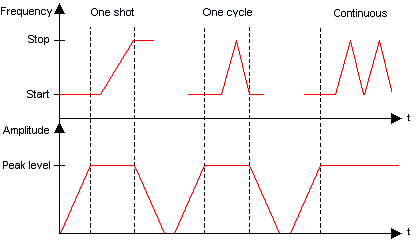
| One shot | The advanced sine sweeps the frequencies from Start Frequency to Stop Frequency and stops. |
| One cycle | The advanced sine sweeps the frequencies from Start Frequency to Stop Frequency, then back to Start Frequency and stops. |
| Continuous | The advanced sine sweeps the frequencies between Start Frequency to Stop Frequency without stopping. |
Hidden/fixed:
| Mode | Sweep | Step | Pure tone |
| Sweep type | visible | visible | hidden |
- Stabilization time: Sweep mode: Selects wait time for the advanced sine at the start frequency and at the right level before starting the sweep. Step mode: Selects wait time for the advanced sine at each step before waiting for the new step event.
- Amplitude 'variation': Maximum length of time for the advanced sine to reach a new level.
- Phase speed: Speed of phase variation when setting a new value for Advanced sine x/ Phase offset setting
- Step: Frequency gap between two steps
Hidden/fixed:
| Mode | Sweep | Step | Pure tone |
| Sweep type | visible | visible | hidden |
- New step: The event that triggers the sweep of the advanced sine to the next step
Hidden/fixed:
| Mode | Sweep | Step | Pure tone |
| Sweep type | hidden | visible | hidden |
Synchro
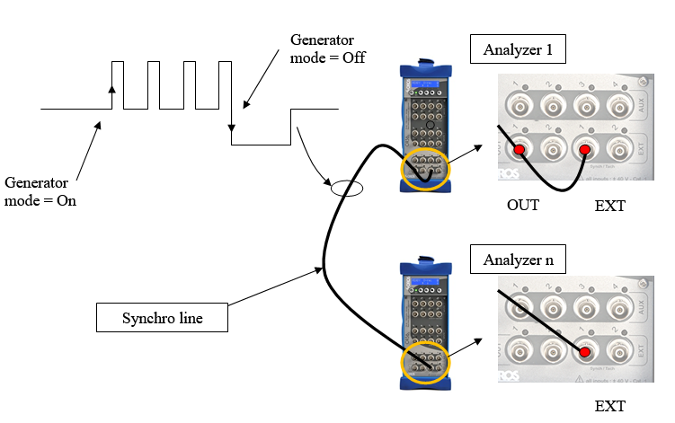
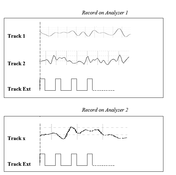
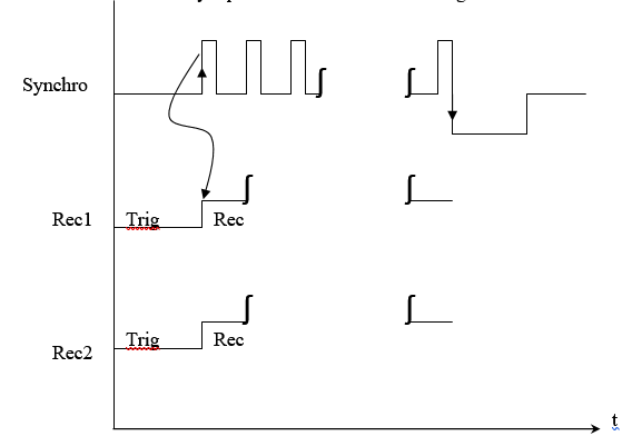
This special output signal is used to synchronize raw data recorded on multiple OR3X units (even OR2X). This synch signal must be connected on ext. synch trigger input of each recording unit (see below)
- Active: On/Off Set the synch signal available in sources list, no signal is generated on outputs at this stage
- Generator Mode: Controls synch signal behavior.
- On: start the synch clock generation (0 / +2 V square @ 50 Hz)
- Off: stop the synch clock generation followed by a -2V step during 1 sec.
Track assembly procedure.
1. Activate the synch signal
2. Select Front-end / Output 1 / source = Synchro
3. Set Front-end / ext synch / coupling = DC on each recording unit
4. Set Front-end / ext synch / threshold = 1 V on each recording unit
5. Set Recorder/trigger/start = ext synch on each recording unit
6. Add ext. sync track to the recorder on each unit
7. Set same recording duration on each unit
8. Run each unit
9. Set generator mode = on to start record
10. Download all recorded files on one PC
11. Launch ’Track Assembler’
The concatenation synopsis is shown on the following scheme:
More information on the Track Assembler in ’Operation on multiples Hardware’.
Listening track
There are 3 ways to listen track:
Input: listen during measurement
Back to the roots of vibration analysis: Everybody knows that our ears and brain is the best instrument to feel and interpret vibration signals. This is also why we take so much care in removing these NVH signals from our machines, vehicles and appliances. The audio playback of vibration (or any other) signal allows the user to "listen in" on what your OROS analyzer is "hearing".
Connect input feature allows a user to play input channels on an output. This allows the user to listen during measurement with an headphone on the output.
Monitor channels : Hot Swap
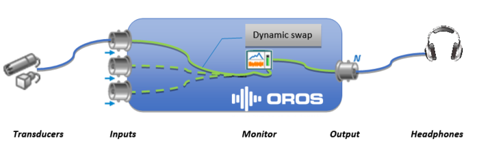
NVgate uses the monitor hot swap capability to allow changing the replicated signal during acquisition/recording.
The NVGate synopsis is as follows:
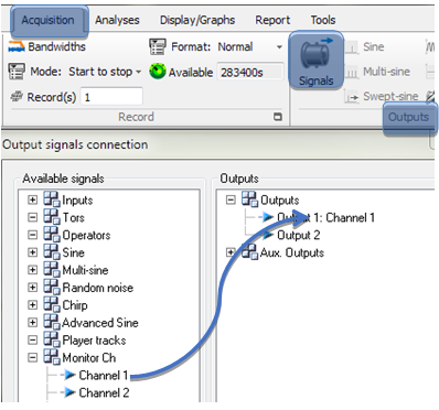
To activate it, simply connect one of the monitor Channels to the desired output from the Acquisition/Outputs/Signal dialog.
Then you can add any front-end input to the monitor channel. The selected input signal will replicate (play) on the output. You can swap from one input to another at any time including during the run and signal recording.
NB: Remember to switch the output impedance to 600 Ω for better listening quality.
Play-Back on PC speaker
If you need to listen a signal already recorded, do not use an output channel. We advice to use the playback on PC speaker defined here: From any of the previous configurations, the recorded signal can be listened to on PC speakers.
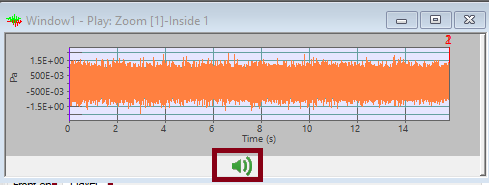
Click on ![]() in the active window. The button stops the play back at any time. A mobile cursor (blue) localizes the played back signal part in the signal window.
in the active window. The button stops the play back at any time. A mobile cursor (blue) localizes the played back signal part in the signal window.
Create and play ANY signal
You can play a signal already recorded with an OROS analyzer, or any signal imported into NVgate. You can put the signal in the player (even in connected mode) allowing the signal to be played on an ouptut channel.
Example : playing a triangle signal on analyzer output
• Generate a triangular signal with an application (Matlab,…) or an online site (example: http://onlinetonegenerator.com/);
• Save this signal in .wav;
• In NVGate, import this signal (File / Import / Files / OR2X Signal (* .wav, .mat, .UFF...);
• Load this signal in the player (right click then "load in player");
• In the options proposed in output, select the channel coming from the player:
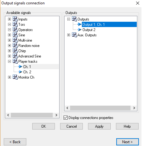
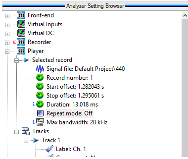
•If you want to play this signal repeatedly, you must change the "Repeat mode" parameter in "Analyzer Setting Browser":

